Goodrive300-19 series open loop vector inverter special for hosit Communication protocol
-212-
· 1 end bit (with checkout), 2 Bit (no checkout)
Error detection field
· CRC
The data format is illustrated as below:
11-bit character frame (BIT1~BIT8 are the data bits)
10-bit character frame (BIT1~BIT7 are the data bits)
In one character frame, the digital bit takes effect. The start bit, check bit and end bit is used to send
the digital bit right to the other device. The digital bit, even/odd checkout and end bit should be set as
the same in real application.
In the RTU mode, the minimum idle time between new frames should be no less than 3.5 bytes. In the
network whose transmission speed is calculated by baud rate, transmission time of 3.5 bytes can be
controlled easily. The data fields are as follows: slave address, operation code, data and CRC
checkout, the byte of each field is hex (0...9, A...F). The network device is always monitoring the
action of communication bus. When the first field (the address message) is received, each device will
confirm the byte. After the final byte is transmitted, there will be another interval time similar to 3.5
bytes to indicate the end of the frame. Later, a new frame will start.
The whole message frame in RTU mode is a continuous transmitting flow. If there is an interval time
(more than 1.5 bytes) before the completion of the frame, the receiving device will renew the
uncompleted message and suppose the next byte as the address field of the new message. As such,
if the new message follows the previous one within the interval time of 3.5 bytes, the receiving device
will deal with it as the same with the previous message. If these two phenomena all happen during the
transmission, the CRC will generate a fault message to respond to the sending devices.
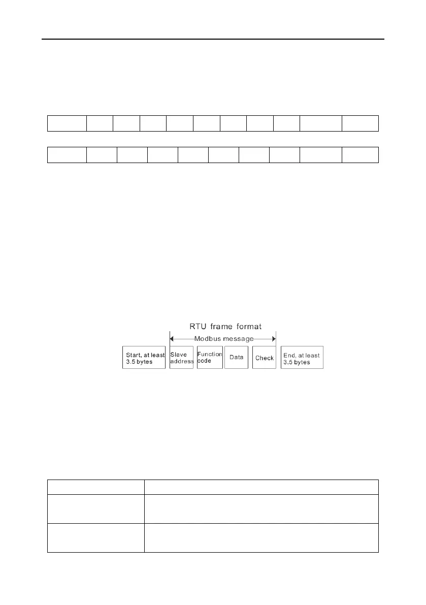
The standard structure of RTU frame:
T1-T2-T3-T4 (transmission time of 3.5 bytes)
Communication address: 0~247 (decimal system) (0 is the broadcast
address)
03H: read slave parameters
06H: write slave parameters

 Loading...


