Goodrive300-19 series open loop vector inverter special for hosit Peripherial options and parts
-243-
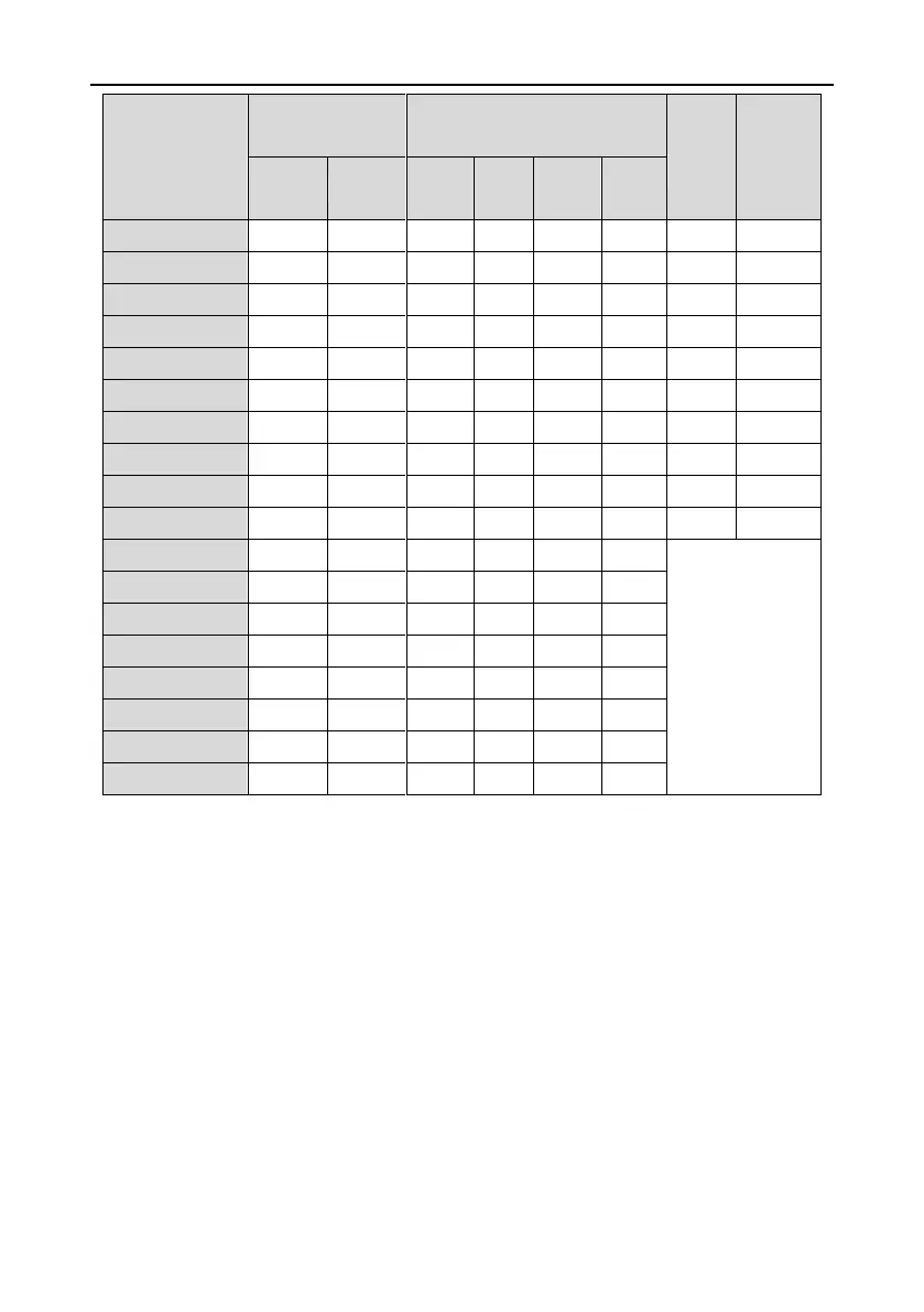
Recommended
cable size (mm
2
)
Connecting cable size (mm
2
)
It is recommended to
use wrench or
sleeve because
screw is used as
terminal.
Note:
1. It is appropriate to use the recommended cable size under 40°C and rated current. The
wiring distance should be no more than 100m.
2. Terminals P1, (+), PB and (-) connect the DC reactor and braking parts.
C.4.3 Routing the cables
Route the motor cable away from other cable routes. Motor cables of several drives can be run in
parallel installed next to each other. It is recommended that the motor cable, input power cable and
control cables are installed on separate trays. Avoid long parallel runs of motor cables with other
cables to decrease electromagnetic interference caused by the rapid changes in the drive output
voltage.
Where control cables must cross power cables make sure that they are arranged at an angle as near
to 90 degrees as possible.

 Loading...


