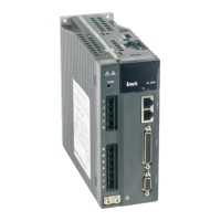
INVT SV-DA200 AC Servo Drive PROFINET Technical Guide V2.63
4
B-phase differential
output -
A-phase differential
output -
A-phase differential
output +
CN1 plug pin layout
CN1 plug signal layout
44 43 42 41 40 39 38 37 36 35 34 33 32 31
30 29 28 27 26 25 24 23 22 21 20 19 18 17
15 14 13 12 11 10 9 8 7 6 5 4 3 2
16
1
OA+ OA- OB- OB+ 24V DI4 - DI2 OCA GND DI5 - - -
OCB - OZ+ OZ- OCZ AO2
RS485+ RS485-
DI7 AO1 AD2 GND DI3 DI6
DO4- DO2+ DO2-
COM-
DO4+ DO3- DO3+ GND AD3 GND GND DO1- DO1+
COM+
DI1
-
The PROFINET servo drive model has two analog inputs, two analog outputs, seven digital inputs, and
four digital differential outputs. The PROFINET servo drive model and the standard model are similar in
the external wiring of analog input, analog output, and digital input. For details, see section 4.5 in DA200
operation manual.
The following shows the external wiring of digital differential output, using DO1 as an example.
Wiring when using the user-provided power supply:
Install this flyback diode
when connecting to
inductive load
Max load-carrying capacity of
each output terminal: 30V,
50mA.
DC
12~24V
+
-
Drive side
Max load-carrying capacity of
each output terminal: 30V,
50mA.
+
-
RY
DC
12~24V
① connect to relay coil ② connect to optical coupler
Connect to a current limit
resistor when connecting to
an optical coupler
Drive side
DO1+ 3
DO1- 4
DO1+ 3
DO1- 4
 Loading...


