INVT SV-DA200 AC Servo Drive PROFINET Technical Guide V2.63
5
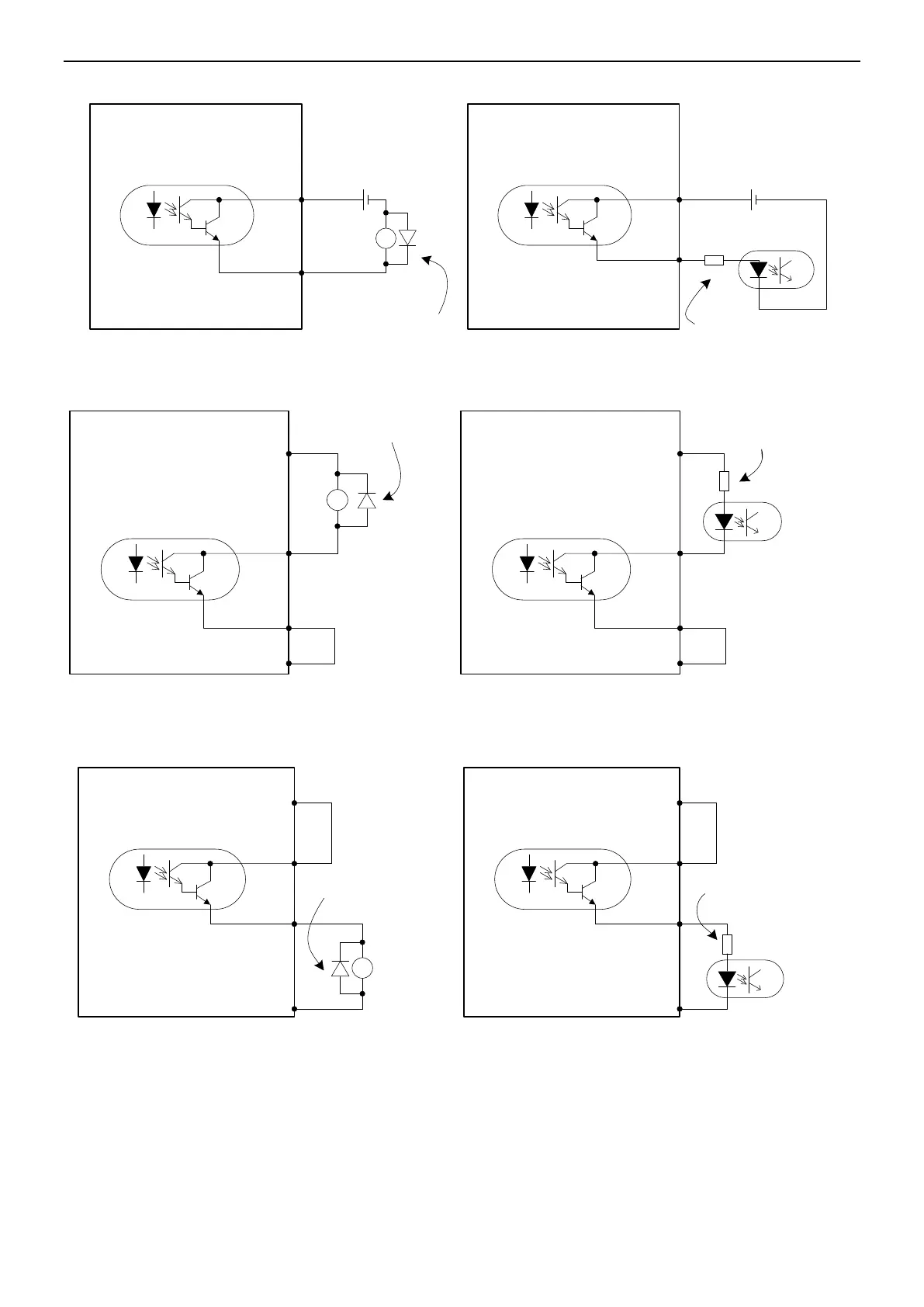
Alternative wiring:
Install this flyback diode
when connecting to
inductive load
Max load-carrying capacity of
each output terminal: 30V,
50mA.
DC
12~24V
Drive side
Max load-carrying capacity of
each output terminal: 30V,
50mA.
DC
12~24V
① connect to relay coil
② connect to optical coupler
Connect to a current limit
resistor when connecting to
an optical coupler
Drive side
+ -
+ -
RY
DO1+ 3
DO1- 4
DO1+ 3
DO1- 4
Wiring when using the local-provided power supply:
Install this flyback diode
when connecting to
inductive load
Max load-carrying capacity of
each output terminal: 30V,
50mA.
Drive side
Max load-carrying capacity of
each output terminal: 30V,
50mA.
RY
① connect to relay coil ② connect to optical coupler
Connect to a current limit
resistor when connecting to
an optical coupler
Drive side
24V 40 24V 40
COM- 12COM- 12
DO1+ 3
DO1- 4
DO1+ 3
DO1- 4
Alternative wiring:
Max load-carrying capacity of
each output terminal: 30V,
50mA.
Drive side
Max load-carrying capacity of
each output terminal: 30V,
50mA.
① connect to relay coil
② connect to optical coupler
DO1+ 3
DO1- 4
Drive side
RY
Install this flyback diode
when connecting to
inductive load
Connect to a current limit
resistor when connecting to
an optical coupler
24V 40 24V 40
COM- 12COM- 12
DO1+ 3
DO1- 4

 Loading...
