SV-DA200 series AC servo drives Faults and solutions
‐136‐
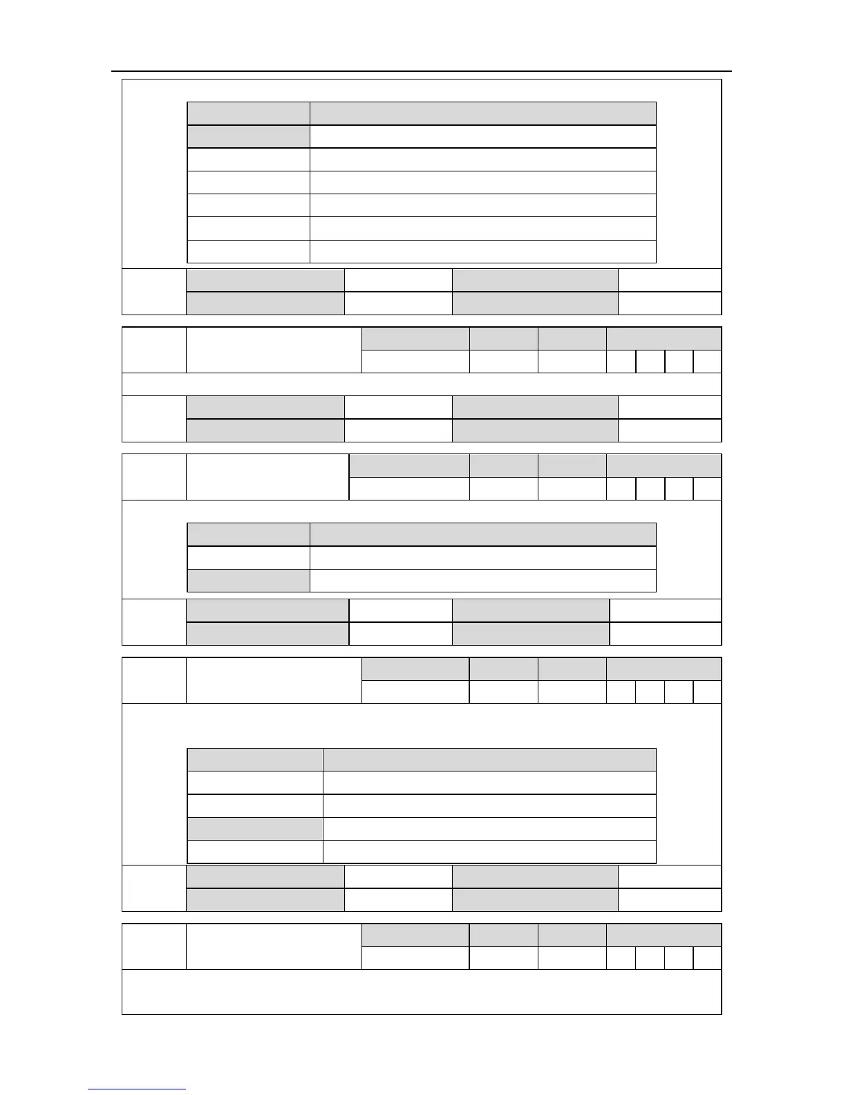
This parameter is used to set the 485 communication parity mode and it only supports RTU mode.
Setting value Baud rate
[0] None (N, 8, 1)
1 Even (E, 8, 1)
2 Odd (O, 8, 1)
3 None(N, 8, 2)
4 Even(E, 8, 2)
5 Odd(O, 8, 2)
P4.04
1
Data size 16bit Data format DEC
Modbus address 1808,1809 CANopen address 0x2404,0x00
P4.05
1
CAN communication node
Setting range Default Unit Available mode
1~127 1 - P S T F
This parameter is used to set the local (salve) CAN communication node no..
P4.05
1
Data size 16bit Data format DEC
Modbus address 1810,1811 CANopen address 0x2405,0x00
P4.06
485 communication fault
clearing mode
Setting range Default Unit Available mode
0~1 1 - P S T F
Set the processing method of the drive during 485 communication fault.
Setting value Meaning
0 Do not clear fault
[1] Clear fault automatically
P4.06
Data size 16bit Data format DEC
Modbus address 1812, 1813 CANopen address 0x2406, 0x00
P4.07
1
EtherCAT synchronous
cycle
Setting range Default Unit Available mode
0~3 2 - P S T F
This parameter is used to the the synchronous interruption cycle of DC sync0 when DC mode is
adopted for EtherCAT communication.
Setting value Meaning
0 250us
1 500us
[2] 1ms
3 2ms
P4.07
1
Data size 16bit Data format DEC
Modbus address 1814, 1815 CANopen address 0x2407, 0x00
P4.08
1
EtherCAT synchronous
type
Setting range Default Unit Available mode
0~2 0 - P S T F
Set the synchronous mode between master station and slave station of EtherCAT
communication.

 Loading...