SV-DA200 series AC servo drives Control mode applications
‐58‐
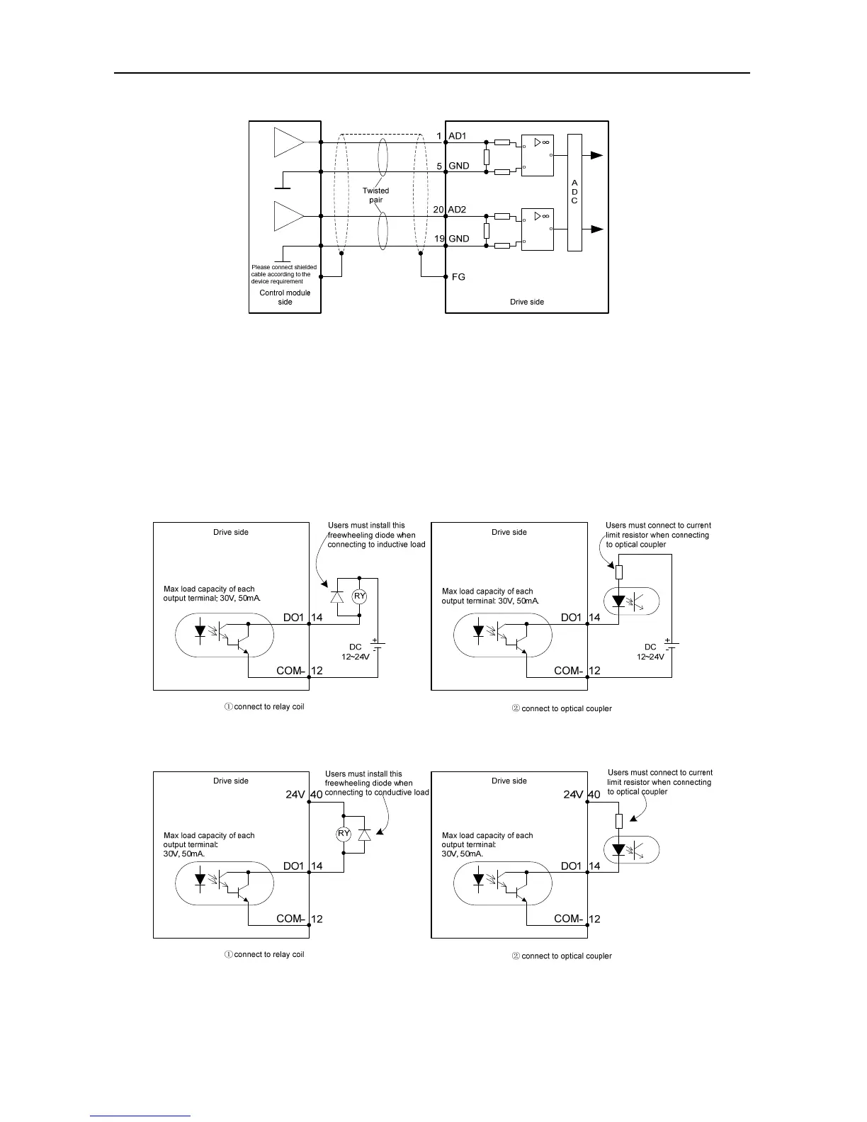
4.5.3 Wiring of the analog input circuit
There are three analog input circuits, AD1, AD2 and AD3, precision of AD1 is 16-bit (optional for
standard models), precision of AD2 and AD3 is 12-bit (standard). The input impedance is 10kΩ. The
input voltage range is -10V~+10V. If the voltage is higher than ±11V, the circuits may be damaged.
If the non-standard model is used as the speed control, AD1 channel is invalid, please take AD3 as
the speed command input terminal and modify P3.70 to “speed command”.
4.5.4 Wiring of digital output circuit
Connection diagram when the power supply is provided by user:
Connection method when the local power supply is used:
There are 6 digital output circuits in total and all of them adopt the open-collector output as shown
 Loading...
