TH4330,4290,4260
48
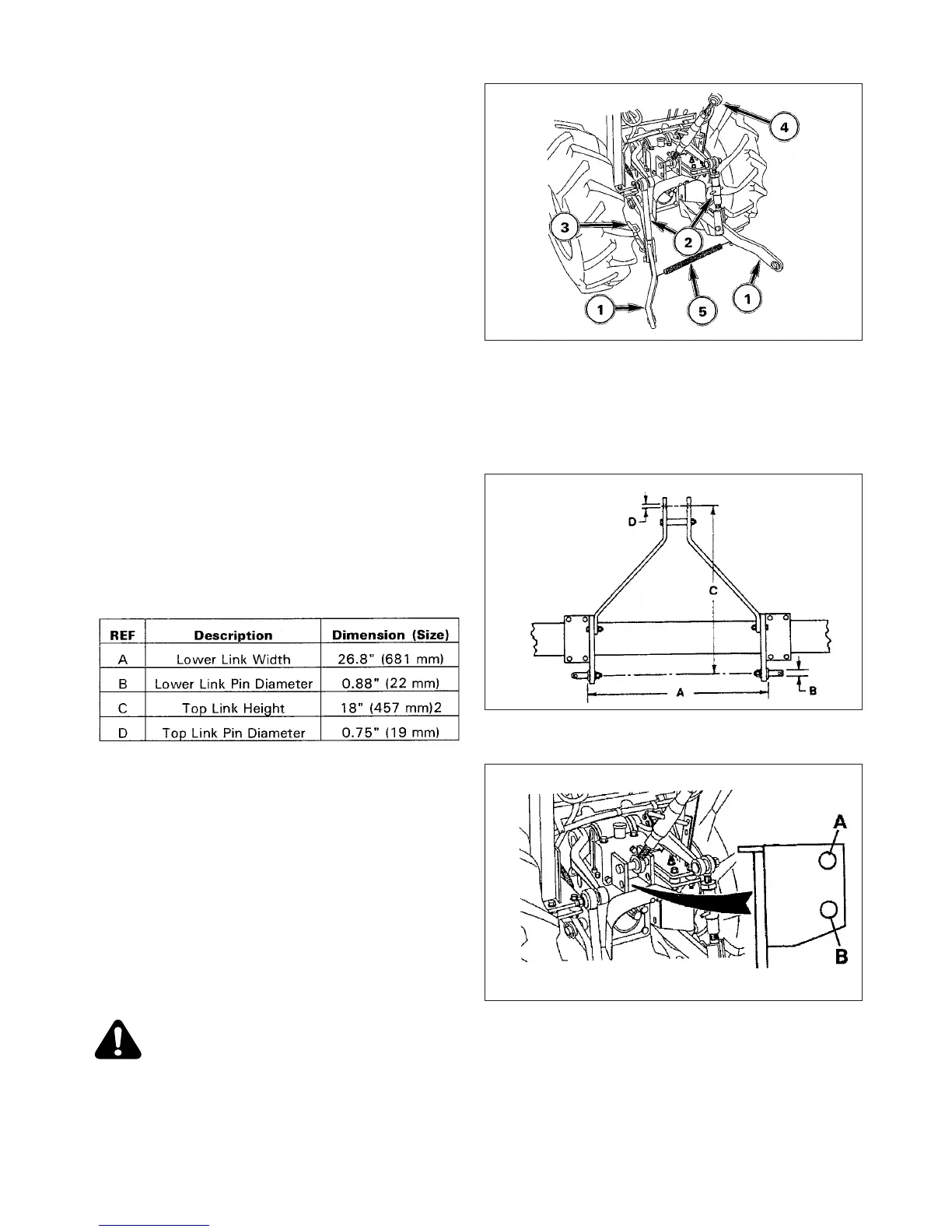
Rear Linkage
FIG. 5-29: Linkage consists of several major components
for implement attachment and operation:
Lower Links, 1 - Primary attaching points to lower imple-
ment pins.
Lift Rods, 2 - Connect lower links to hydraulic lift arms
for raising/lowering of lower links. The lift rod connected
to the right lower link has provisions for leveling the
implement (side to side).
Stabilizer, 3 - Reduce side sway of implement.
Top Link, 4 - Adjustable, turnbuckle type to level imple-
ment (front to rear). Top link also provides draft load
sensing for draft control.
Check Strap, 5 - Secures lower links together to prevent
tire interference when hitch Is not used.
FIG. 5-30: To match varying implements, rear linkage is
standardized according to spacing, pin size, etc. This
enables usage of alternate implements with minimal
adjustments as long as matching size or “Category” of
implement is used.
This Tractor is equipped for “Category I” implements with
following attaching point dimensions.
FIG. 5-31: Linkage provides two positions of connecting
top link to Tractor.
For most implements, securing top link in upper hole, A,
is satisfactory, but position may be varied to provide
increased implement height during transport.
If draft control is installed, these positions are also used
to adjust draft sensitivity:
Use upper hole, A, for implements with low draft, or for
more sensitivity.
Use lower hole, B, for high draft implements, or for less
sensitivity.
CAUTION: Secure all pins after adjustment is
made. Always use pins supplied with Tractor.
FIG. 5-29
FIG. 5-30
FIG. 5-31
 Loading...