OPERATION
53
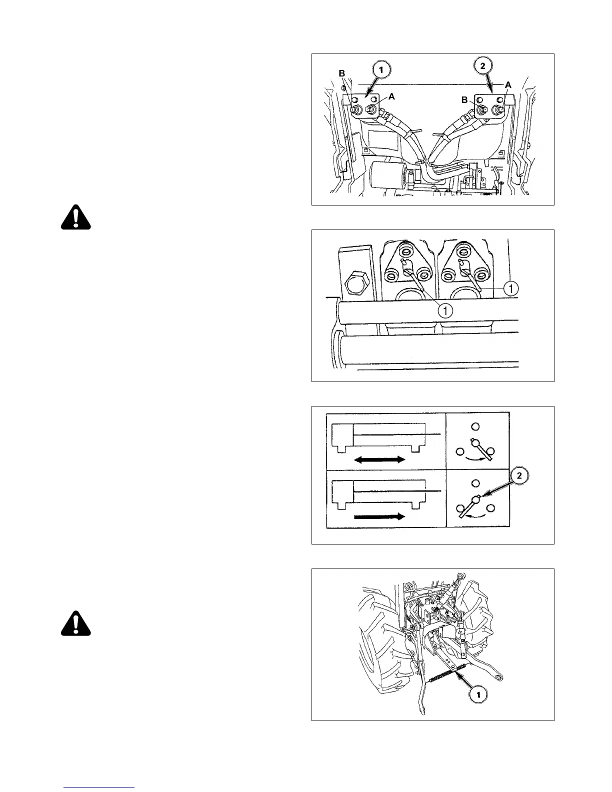
FIG. 5-41: Remote couplers are located at rear of
Tractor, above three-point hitch. Coupler set, 1, corre-
sponds with control lever, 1, (Fig. 5-40), coupler set , 2,
with control lever, 2 (Fig. 5-40).
Implement hoses must be connected to each coupler set
so when respective control lever is pulled rearward,
implement raises and when pushed forward, implement
lowers. Male coupler tips (on implement hoses) must be
compatible with Tractor couplers and must also be insert-
ed fully and locked into Tractor couplers to operate cor-
rectly.
CAUTION: Always lower implement to
ground, shut off engine and relieve system
pressure (by operating control levers with
engine off) before connecting or disconnect-
ing implement hoses.
CAUTION: Make sure all hydraulic hoses,
couplers and cylinders are in good condition
before use. Damaged equipment is danger-
ous.
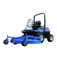
FIGS. 5-42 & 5-43: Most implements require double-act-
ing hydraulics. Each implement cylinder will have two
hoses connected to it.
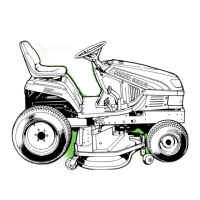
When single-acting service is required (cylinder with only
one hose), the inner coupler, 1, will be used and selector
function, 2, located at right rear of tractor, must be turned
to the left.
NOTE: For normal double-acting operation, selector
function must be turned to the right.
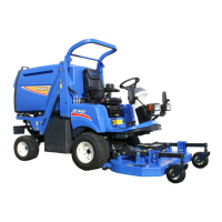
Disconnect lower links from implement pins. Make sure
lower links are connected together with spring, 1, to pre-
vent tire interference.
Take position in operator’s seat, start engine and drive
Tractor clean of implement.
DRAWBAR
FIG. 5-44: Drawbar, 1, at rear of Tractor allows pull-type
implements to be attached Tractor. Maximum vertical
load on drawbar must not exceed 750 lbs (340kg).
CAUTION: Pulling heavy loads will require
extended braking distances. Reduce travel
speed.
Make sure attachment is properly secured and safety
chain is used.
NOTE: When using three-point hitch, it may be neces-
sary to remove drawbar by removing clip and pin,
and sliding drawbar from bracket to improve
operating clearance. This is particularly true with
mounted implements using PTO drive.
FIG. 5-41
FIG. 5-42
FIG. 5-43
FIG. 5-44