OPERATION
49
Attaching Implements
CAUTION: Always use POSITION CONTROL
to attach / detach implements to provide pre-
cise control hitch.
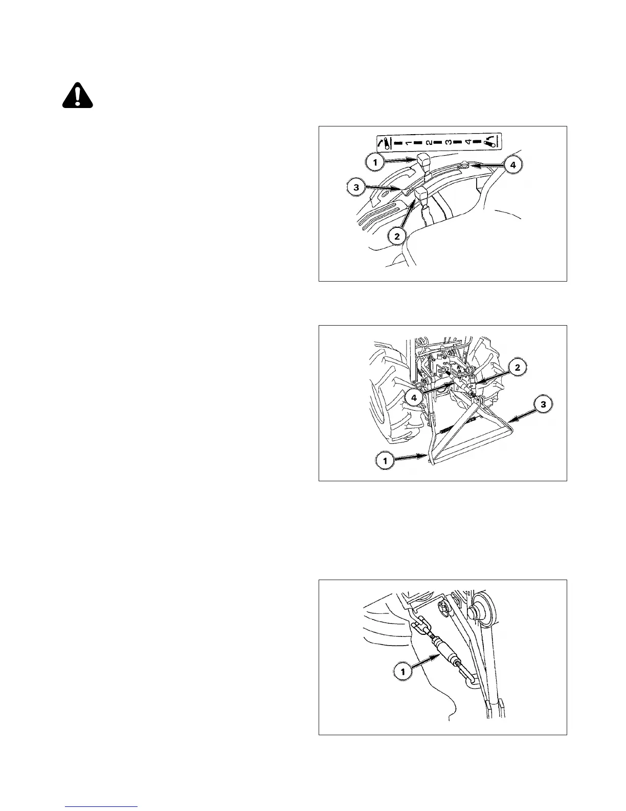
FIG. 5-32: Back Tractor to implement, centering Tractor
with implement hitch frame. Place draft control lever, 2 (if
installed), in fully lowered position as it will not be used.
Raise or lower hitch using position control lever, 1, and
align left lower link end with corresponding implement
attaching pin.
Lock the brakes, shut off engine and remove key.
NOTE: Front lever stop, 3, can be set to contact position
control lever in implement work position. This
enables implement to be returned to identical
position after hitch has been raised for turning,
transporting, etc. Rear lever stop, 4, can be set
to limit raising height, if required.
FIG. 5-33: Slide ball end of left lower link, 1, over imple-
ment pin and secure with lynch pin.
Adjust height of right lower link using turn buckle, 2.
Attach and secure right lower link, 3, to implement with
lynch pin.
Attach top link, 4, to top of implement hitch frame using
pin supplied with Tractor. Rotate center barrel section of
top link, to lengthen or shorten, and level implement from
front to rear.
After the implement is attached, adjusted for level opera-
tion (as needed) using lift rod and top link turn buckles.
Secure all adjustments.
IMPORTANT: With some three-point hitch “mounted”
implements, it will be necessary to remove
drawbar at rear of Tractor to permit imple-
ment to be raised and lowered without
obstruction.
FIG. 5-34: Certain implements require minimal side-play.
Stabilizer, 1, at each lower link should be evenly adjusted
to reduce side-play to desirable level. Do not remove all
side-play as lower link damage may result. Linkage pro-
vides two positions of connecting top link to Tractor.
NOTE: The amount of side-play (stabilizer looseness) is
dependent upon implement and type of opera-
tion. Normally 2” (50mm) of total side movement
is desired, 1” (25mm) to each side to Tractor
centerline.
FIG. 5-32
FIG. 5-33
FIG. 5-34
 Loading...