TH4330,4290,4260
50
Using Position Control
Type of Work – Attaching / detaching implements and
other operations requiring implement to be kept at con-
stant height above ground. Also used with toll bars having
flexible row units and implements equipped with gauge
(support) wheels.
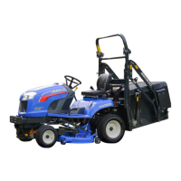
FIG. 5-35: Lever Positions – Draft control lever, 2 (if
equipped), fully down (not used). Use position control
lever, 1, to adjust hitch and implement position.
NOTE: Front lever stop, 3, can be set to contact position
control lever in implement work position. This
enables implement to be returned to identical
position after hitch has been raised for turning,
transporting, etc. Rear lever stop, 4, can be set
to limit raising height, if required.
To Begin Work – Align Tractor and implement in field
and move position control lever, 1, forward (toward
DOWN). Adjust implement height using position control
lever and sent adjustable stops, 3, and 4, as desired.
When Turning – Move position lever, 1, rearward
(toward UP) to raise implement. Finish turning and return
lever against stop to resume operation.
To Finish Work and Transport – Move position control
lever, 1, fully rearward in quadrant.
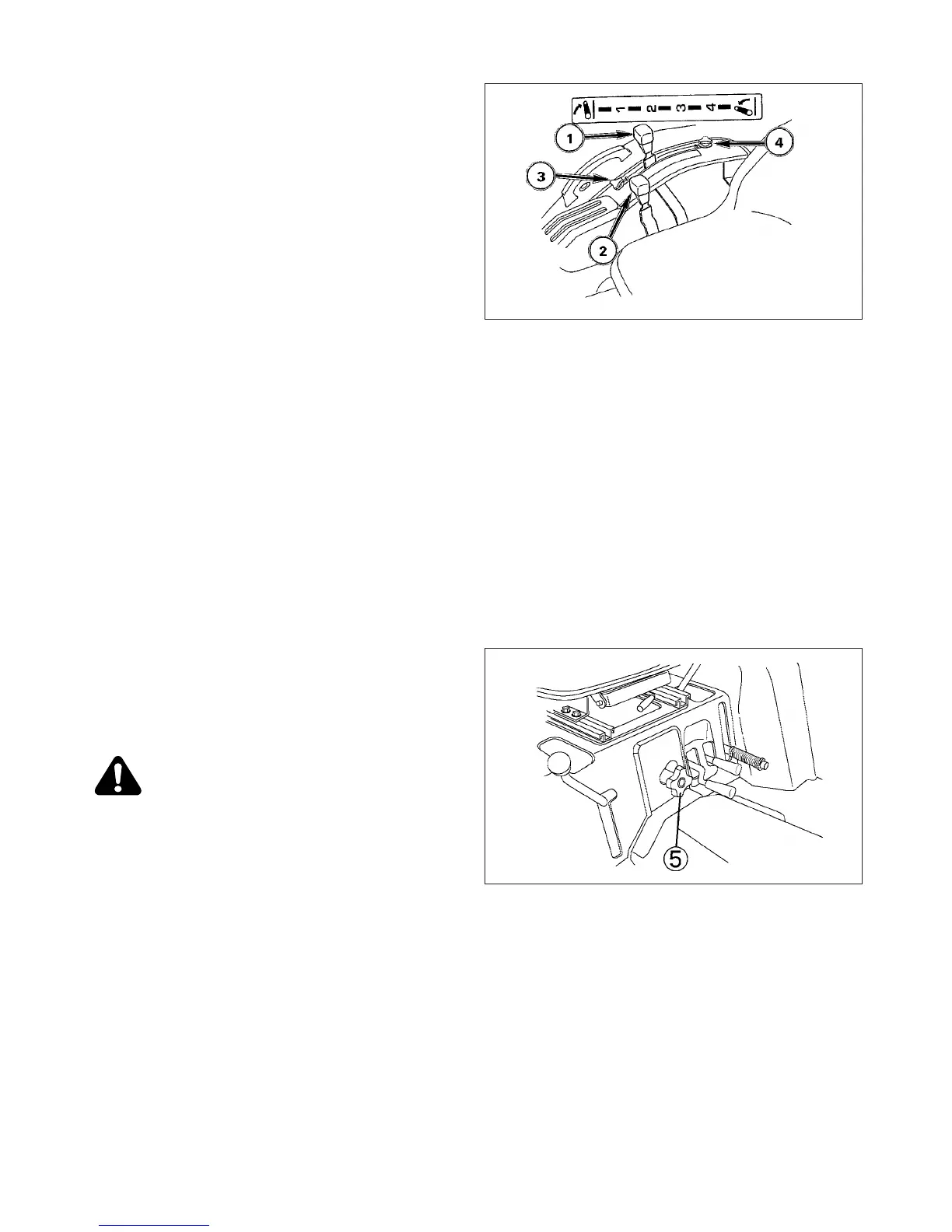
FIG. 5-36: Lowering speed can be readjusted as neces-
sary using lowering rate control knob, 5.
Turning lowering speed knob fully clockwise will prevent
links from lowering.
CAUTION: When using mounted implements
with PTO driveline, make sure:
PTO drive shaft has minimum 51 mm (2”)
engagement of telescoping sections, at all
hitch / implement positions.
Hitch height during raising does not bind
drive shaft universal joints due to extreme
drive shaft angles. Limiting raising height
may be required.
PTO drive is disengaged during transport.
FIG. 5-36
FIG. 5-35
 Loading...