EasyManuals Logo

Iseo X1R Smart User Manual

Iseo X1R Smart
72 pages
To Next Page IconTo Next Page
To Previous Page IconTo Previous Page
Page #25 background imageLoading...
Page #25 background image
25
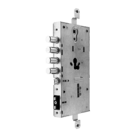
See below a real picture of the lock, with all connectors’ description.
Overview
Batteries power supply
External control module: Bluetooth radio
cable.
Internal control module
External control module: keyboard, and
RFID reader cable.
8 Poles Multifunction Cable connector.
“Not use” connectors are for future developments.
To use the Door sensor contact in the hinges side of the door, an x1R specific code is
required (not standard solution). For more info go to Door sensor contact paragraph.
To know more about Actuator mode go to x1R Smart as Actuator paragraph.
When the door is closed and safe (bolts fully extended), the relay normally closed
contact (NC), is closed. When the door opens the NC opens. For more detailed
information about the relay behavior go to Door status relay paragraph.
JP1 connector for Actuator mode.
Door sensor contact connectors when
installed in the hinges side of the door
(same equals connectors)
Not used
Not used

Other manuals for Iseo X1R Smart

Questions and Answers:

Question and Answer IconNeed help?

Do you have a question about the Iseo X1R Smart and is the answer not in the manual?

Iseo X1R Smart Specifications

General IconGeneral
BrandIseo
ModelX1R Smart
CategoryLocks
LanguageEnglish

Related product manuals