EasyManua.ls Logo

iSMA MINI Series - 6.4 Registers 40141-40155

iSMA MINI Series
73 pages
Print Icon
To Next Page IconTo Next Page
To Previous Page IconTo Previous Page
Loading...
MINI and MIX Series I/O modules/Modbus
version 1.3 www.gc5.pl Page 57 / 73
Modbus
Addr
Dec
Addr
Hex
Addr
Register name
Access
Description
OUTPUT 2
Write
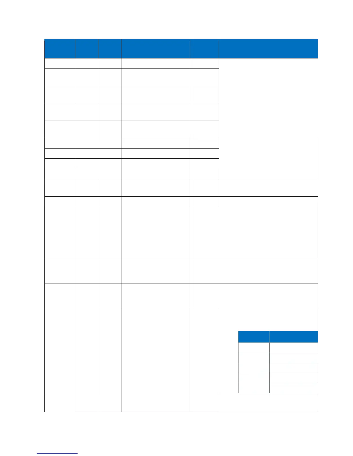
in the mV range from 0 to 10000mV
40123
122
0x7A
VALUE OF ANALOG
OUTPUT 3
Read &
Write
40124
123
0x7B
VALUE OF ANALOG
OUTPUT 4
Read &
Write
40125
124
0x7C
VALUE OF ANALOG
OUTPUT 5
Read &
Write
40126
125
0x7D
VALUE OF ANALOG
OUTPUT 6
Read &
Write
30125
124
0x7C
HAND STATUS VALUE 1
Read Only
The current value of Analog Output in
the hand mode for MINI with AO
30126
125
0x7D
HAND STATUS VALUE 2
Read Only
30127
126
0x7E
HAND STATUS VALUE 3
Read Only
30128
127
0x7F
HAND STATUS VALUE 4
Read Only
30130
129
0x81
HARDWARE_VERSION
Read Only
The current hardware version of a
device
30131
130
0x82
MAC_ADDRESS (32 – bits)
Read Only
The MAC address of a device
40136
135
0x87
BAUD RATE
Read &
Write
Memory
Transmission speed is defined by the
user calculated using the formula:
 󰇛󰇜 
The value is considered only when
sections 1, 2 and 3 of S3 switch is in the
OFF position
The default value is 7680 (76800 bps)
40137
136
0x88
STOP BITS
Read &
Write
Memory
Supported values are 1 and 2
The default value 1
40138
137
0x89
DATA BITS
Read &
Write
Memory
Supported values are 7 and 8
The default value 8
40139
138
0x8A
PARITY BIT
Read &
Write
Memory
Parity bit (40139) The default value is 0
(no parity)
Allowed values:
Value
Description
0 (default)
none
1
Odd
2
Even
3
Always 1
4
Always 0
40140
139
0x8B
RESPONSE DELAY
Read &
Write
Delay in ms before sending response
The default value is 0.

Table of Contents

Related product manuals