6D3 – 10 CHARGING SYSTEM
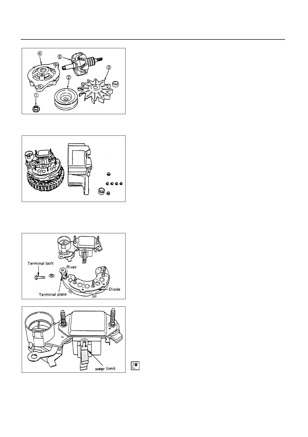
6. Rotor
• With the rotor gripped with a vise, remove the pulley
nut
!
, and then take off the pulley
"
, fan
#
, front
cover
$
and the rotor
%
.
7. Rear Bearing
8. Terminal Bolt and Nut
9. Rear Cover
• Remove the nuts fixing the B terminal and diode
holder.
Separate the stator and rear cover.
Note the position of insulation washers to ensure
reassembly into original position.
10. Stator
11. Diode
• Separate the diodes from the stator by melting away
solder on stator coil and diode.
When melting solder, hold the lead wire with long nose
pliers to prevent heat from being transferred to the
diodes.
12. IC Regulator Assembly
• Separate the IC regulator from the diode by melting
away solder on IC regulator holder plate and removing
the nut.
13. Brush Holder
• Remove the serrated bolts and melt away solder on IC
regulator.
• Do not remove the serrated bolts unless the
replacement of brush or condenser.
To install, follow the removal steps in the reverse
order.
INSPECTION AND REPAIR
Repair or replace necessary parts if extreme wear or
damage is found during inspection.
6D3-10-1.tif
6D3-10-3.tif
6D3-10-4.tif
6D3-10-2.tif
 Loading...


