EXHAUST GAS RECIRCULATION (EGR) SYSTEM 6E– 3
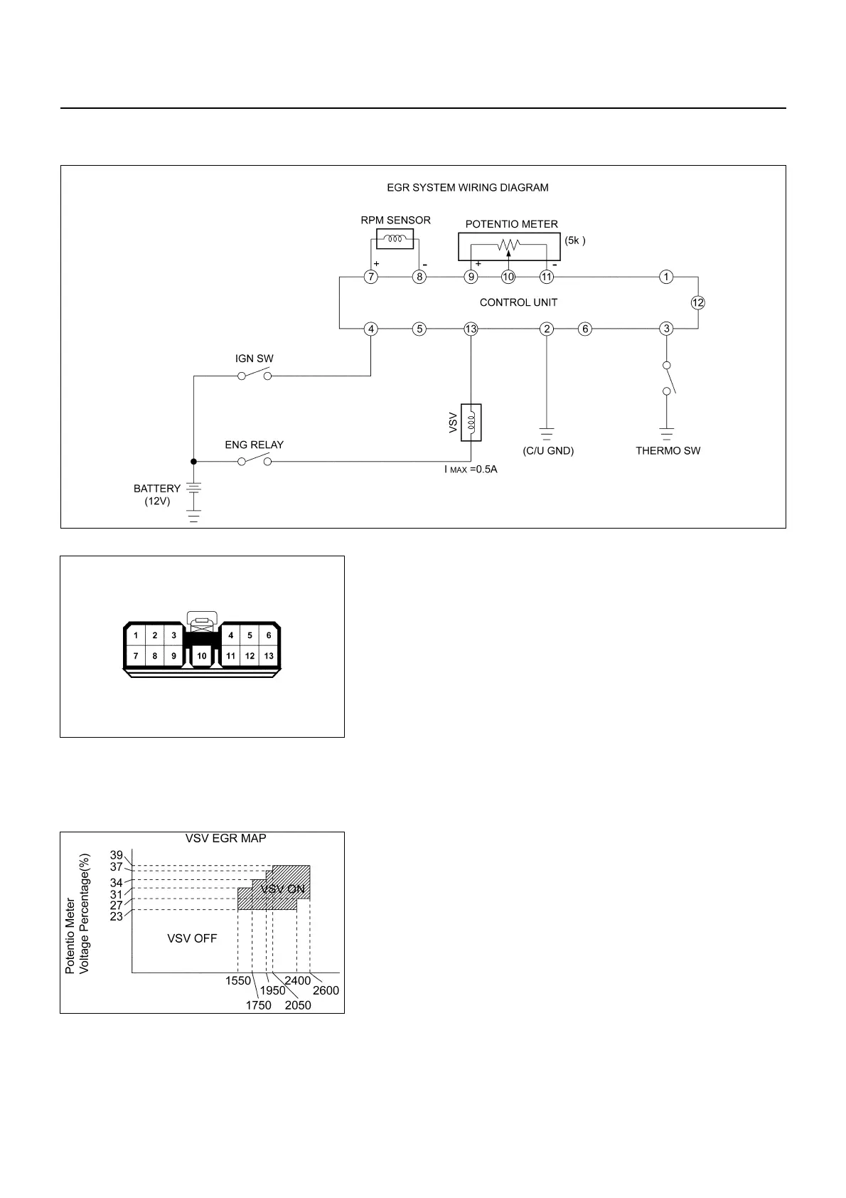
EGR SYSTEM WIRING DIAGRAM
1. CONNECTOR PIN ASSIGNMENT
No. CONNECTOR NAME
1-
2 Battery (-) c/u GND
3 Thermo Switch
4 Battery (+)
5-
6-
7 rpm Signal (+)
8 rpm Signal (-)
9 Potentio Meter (+)
10 Potentio Meter
11 Potentio Meter (-)
12 -
13 VSV
EGR SYSTEM OPERATION
1) On the input side of engine speed, there is provided a
hysteresis of 50 rpm on the speed rising side.
2) It does not work until 70 sec, pass after engine start.
3) It does not work while the water temperature switch is
on (30°C or lower).
4) While engine speed drops from 3,800 rpm or higher, it
does not work for 25 sec.
13-01.tif
056LX016.tif
826LX007.tif
(above 40
℃
: OFF)
(below 30
℃
: ON)
 Loading...


