6D3 – 20 CHARGING SYSTEM
In this case, the slip ring can be used until its outer
diameter becomes 0.4mm shorter than the initial size.
5) Rectifier
Conduct a rectifier continuity test using the KΩ range
of a circuit tester.
Specifically, change polarity between the rectifier and
holder fin, making sure that there continuity in either
one direction only. (There should not be continuity in
the other direction.)
NOTE:
It is impossible to judge a rectifier by the resistance in
the direction of easy flow. Because of diode’s
characteristics, the current in the direction of easy
flow changes greatly depending on the power source
voltage.
Therefore, a tester’s indication varies depending on
its type and resistance range variation.
Accordingly, it must be regarded as a criterion that
there is a wide difference between the resistances
easy flow and the other direction.
Never use a 500V megohmmeter for such a continuity
test, since the rectifier may be damaged.
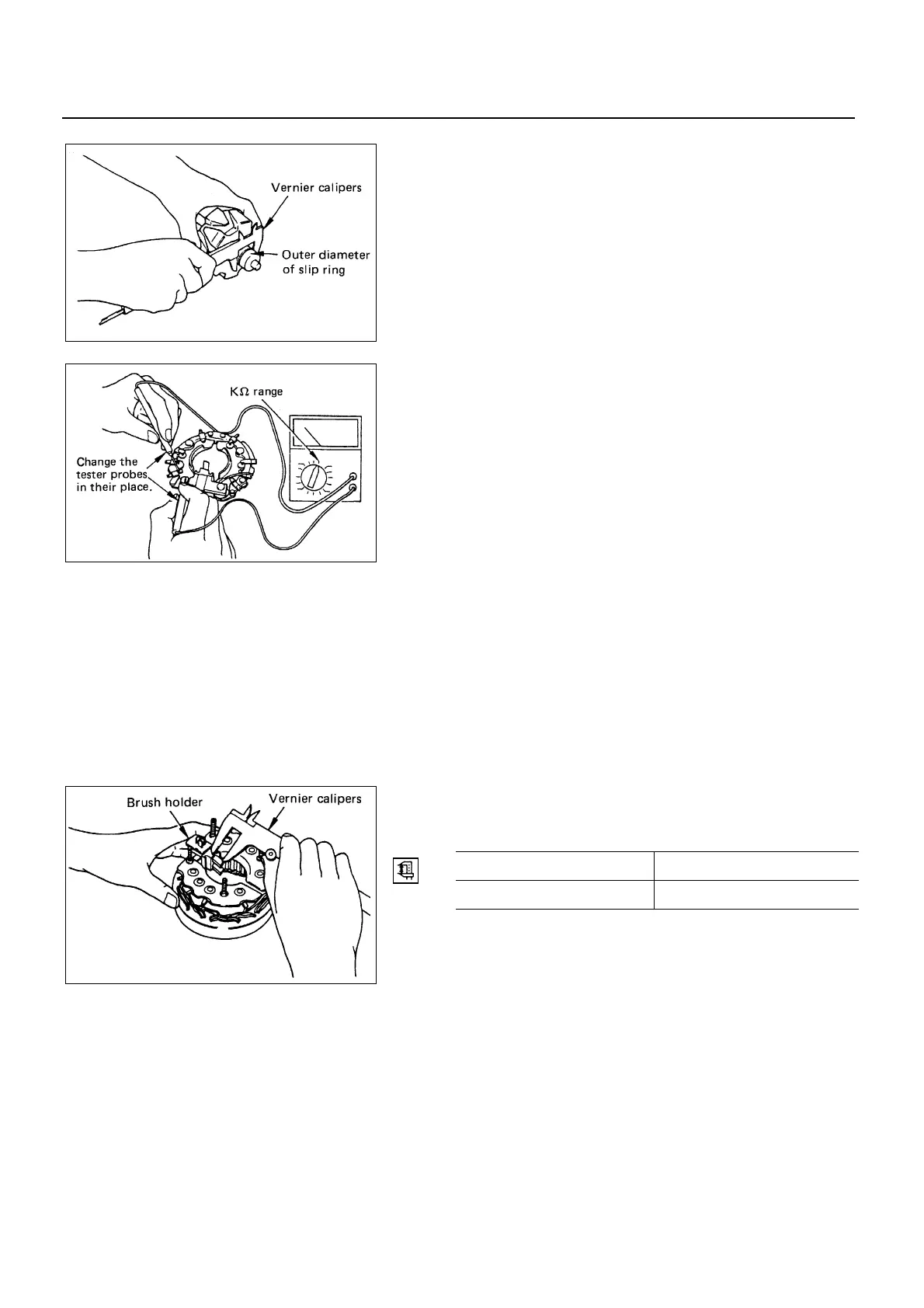
6) Brush
Measure the protruding length from the brush holder.
mm (in)
Standard Limit
12.5 (0.492) 5.5 (0.217)
6D3-20-1.tif
6D3-20-2.tif
6D3-20-3.tif
 Loading...


