Inspection and Installation
Copyright © Itech Electronic Co., Ltd. 19
2. Connect one pair of induction wires from the S+ and S- to the DUT.
3. Connect one pair of drive wires from the positive and negative terminals on
the front panel or the + and - terminals on the rear panel to the DUT.
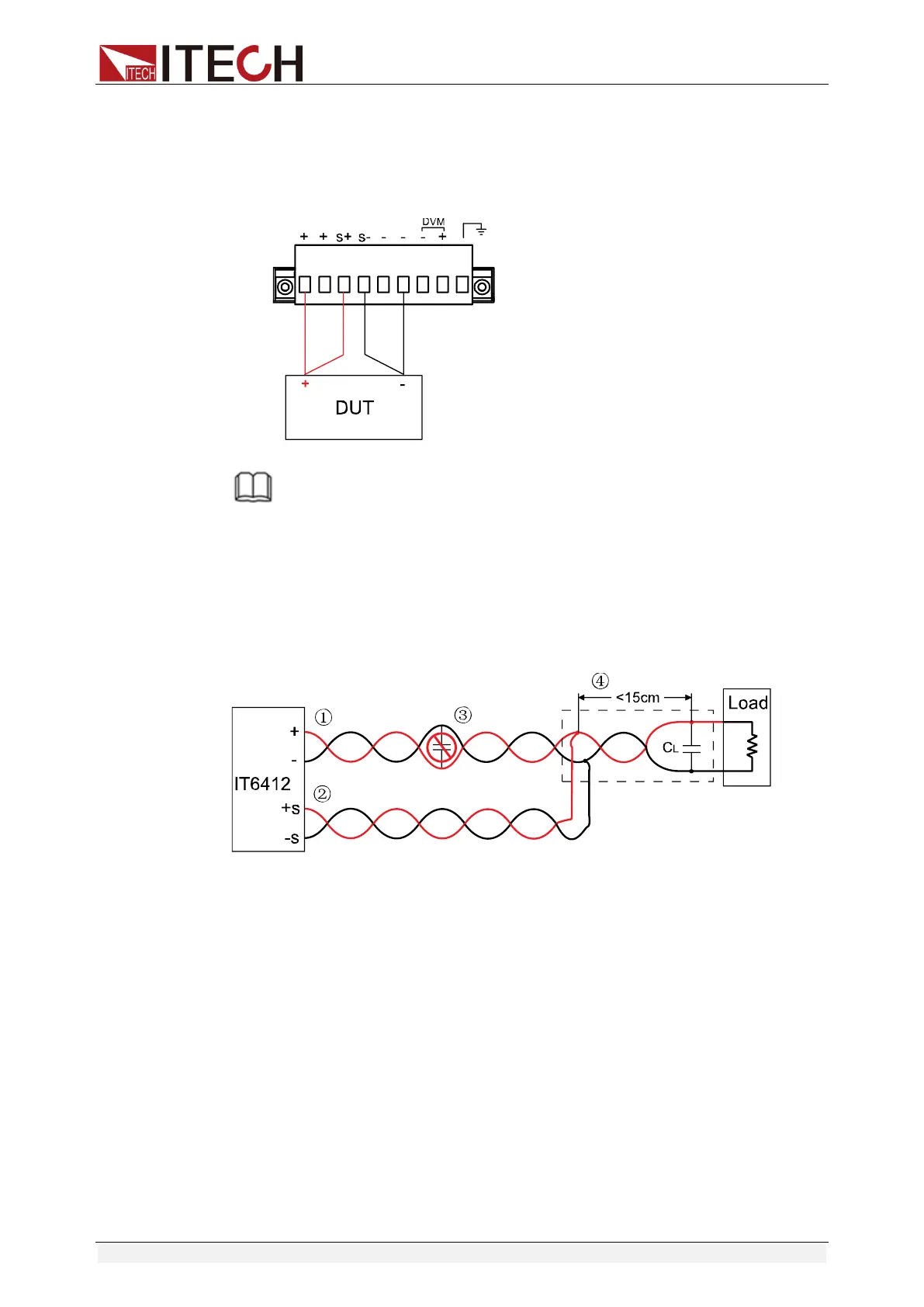
Wiring Schematic Diagram of Remote Measurement is as follows:
NOTE
To ensure system stability, please apply armored twisted-pair cables between the IT6400
series power supply remote measurement and DUT. Do not twist the sense connection wires
and the load wires. To prevent damage, please pay special attention to positive and negative
polarities of power supply during connection! When the remote measurement function is not
used, do not leave the Sense terminal suspended!
Use of capacitor in circuit:
If capacitor is used in circuit, the installation position should be as shown below:
① Load wires must be twisted-pair or coax and must not be twisted with the
sense wires.
② Sense wires must be twisted-pair or coax and must not be twisted with the
load wires.
③ No capacitors are allowed within the sense-compensated load path.
④ If the load capacitor (C
L
) is not located at the sense point, the distance from
the sense point to the load capacitor cannot exceed 15cm and must be
twisted-pair, coax, or pc traces.
Connection of DVM
IT6400 series power supply is built in with a digital voltmeter (DVM), which can
be used for measuring external voltage.
DVM measurement wiring is as follows: