Inspection and Installation
Copyright © Itech Electronic Co., Ltd. 18
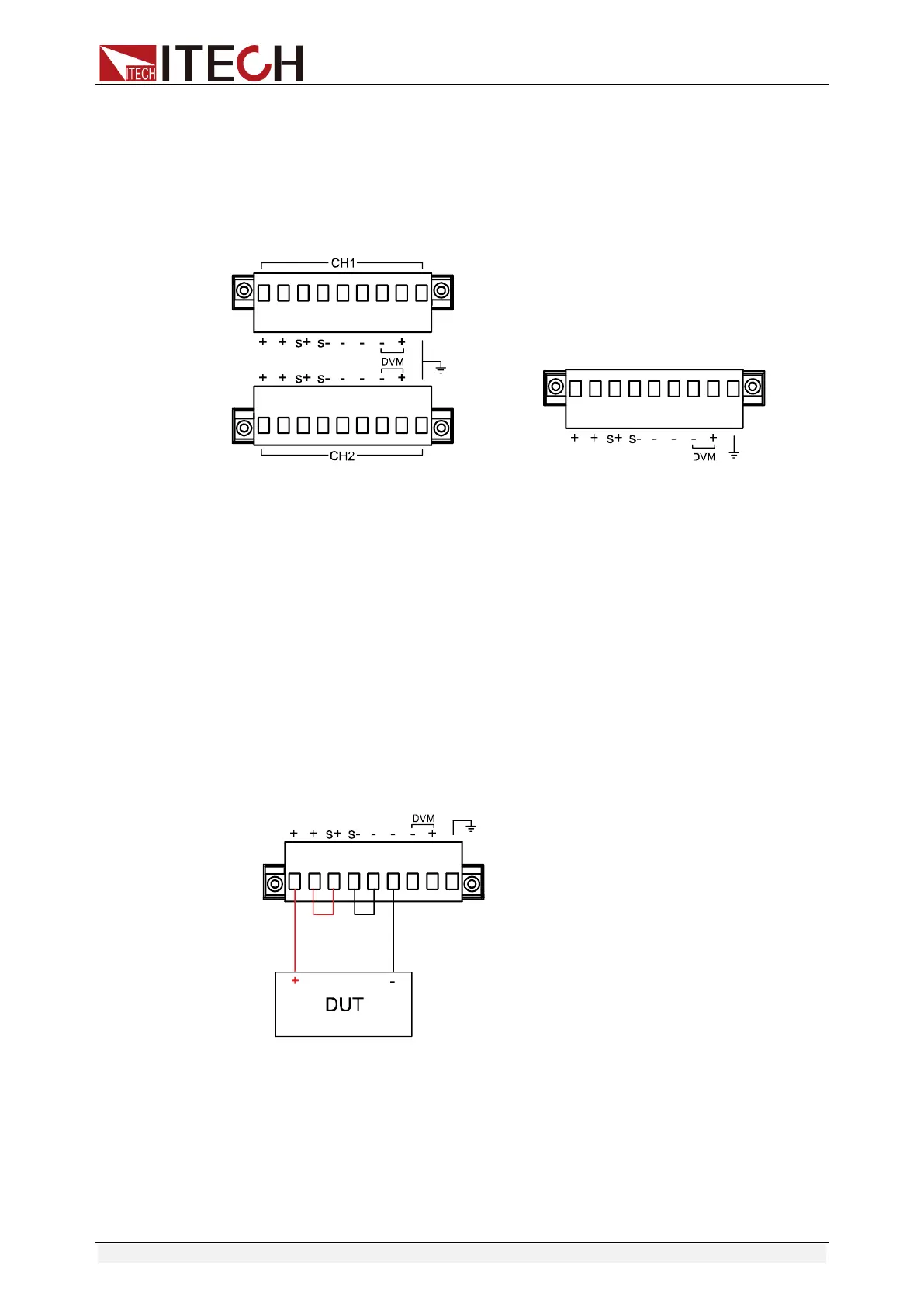
Schematic Diagram of S+/S- and +/- Rear Panel:
When the DUT consumes high current, voltage drop will appear at the
connecting wire between the power supply and the DUT terminals. To ensure
measurement accuracy, a remote measurement terminal is provided at the rear
panel of the power supply, from which, the User may measure the input
terminal voltage of the DUT.
Dual-channel power supply Single-channel power supply
⚫ S+/S-: Remote measurement terminal: when remote measurement
function is applied, lead out the “S+ and S-” for connecting the DUT.
⚫ +/-: Output terminal.
Use local measurement:
The local measurement does not compensate the voltage drop on the wires.
The operations are as follows:
1. Use the shorting clip on the rear panel or directly install wires between +
and S+ as well as - and S-.
2. Connect the output of positive and negative terminals on the front panel or
the + and - terminals on the rear panel to the DUT through wires.
Wiring Schematic Diagram of Local Measurement is as follows:
Use remote measurement:
The remote measurement function allows compensation for voltage drop of the
electric wires between the power supply output terminal and the DUT.
Operations are as follows:
1. Remove any wire jumpers or shorting clips between the + and S+ as well
as between the - and S- of the terminal board connector on the rear panel.