Basic Operation
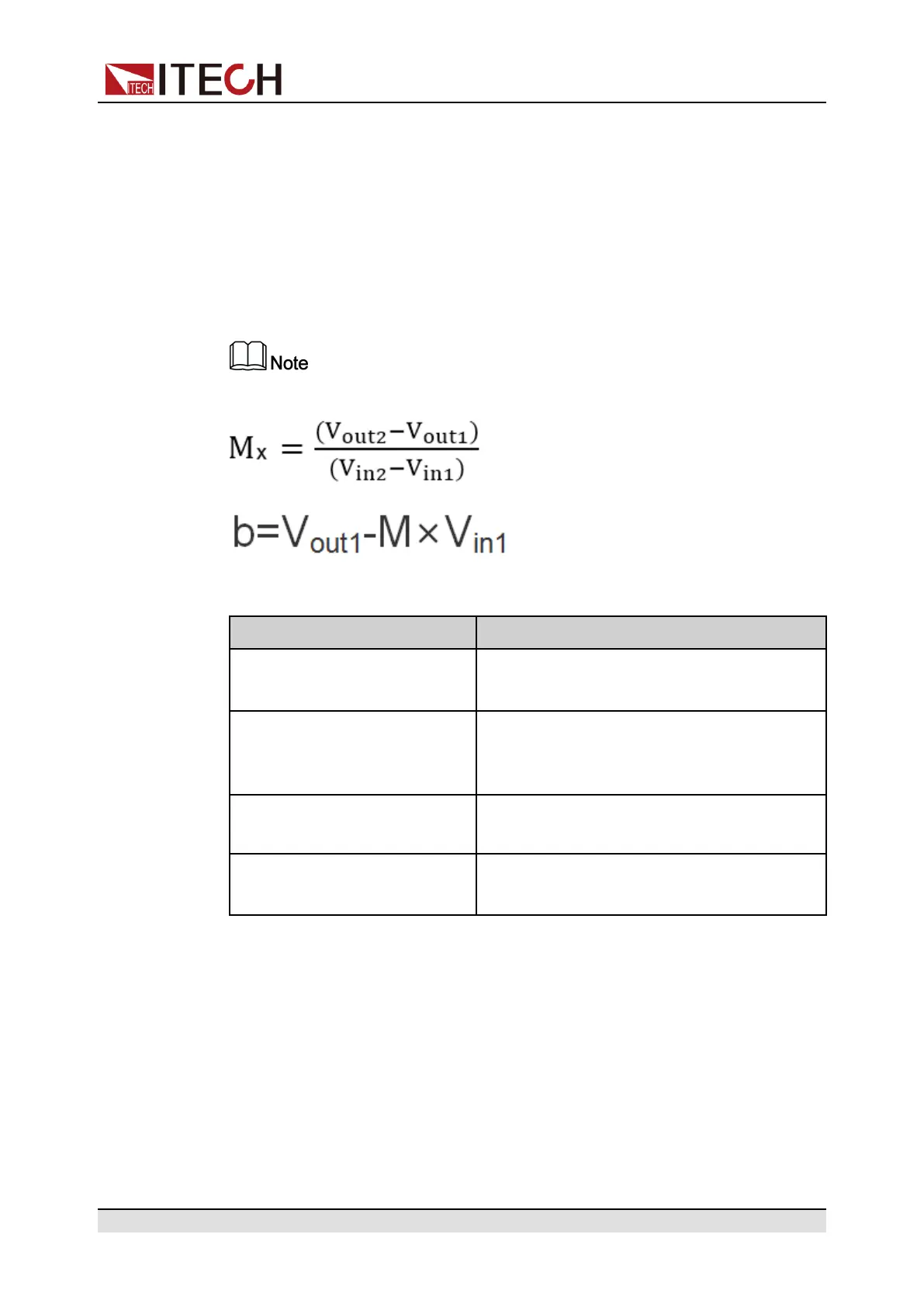
all follow the calculation relationship of y=Mx+b. The user needs to set the M
(slope coefficient) and b (offset) values in different modes in the analog quantity
menu. For calculation of the analog quantity value. The user can calculate the
M and b values based on the analog requirements in accordance with the for-
mula below.
Taking the CV program setting as an example, the user needs to convert the M
and b values based on the formula below. And set these two values respectively
through the front panel keys (or the SCPI remote command).
The setting principles of calculation parameters in other modes are the same.
Formula parameter descriptions:
Name Description
V
in1
Indicates the start voltage input to pin 8. The
setting range is from –10 to 10.
V
in2
Indicates the end voltage input to pin 8. The
setting range is from –10 to 10, and V
in2
>
V
in1
.
V
out1
The starting value of the input voltage in CV
mode.
V
out2
The end value of the input voltage in CV
mode, and V
out2
> V
out1
.
Analog Control
The pin connection method and instrument operation method in four basic
modes of the load are the same. The voltage control in CV mode is taken as an
example below to describe the connection and usage.
1. Refer to the figure below to complete the pin connection.
Copyright © Itech Electronic Co., Ltd.
101
 Loading...