67
07610-003-78-18-N
16
13
12
10
9
8
7
5
4
321
MAIN ELECTRICAL
CONNECTION
6
15
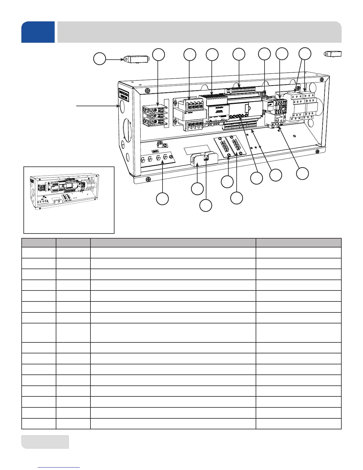
208-230V Blower Control Box
does not include the Transformer (#2)
and Power Supply (#3).
ITEM QTY DESCRIPTION PART NUMBER
1 1 Terminal Block, 115A, 600V 05940-004-08-35
2 1 Transformer, 208/230/460 to 120 (0.05 KVA) 05940-004-09-18
3 1 Power Supply, 120V, 24VDC, 2A 05950-003-76-32
4 1 Terminals 05700-004-05-08
5 1 Relay Socket, 16A, 300V 05945-003-79-58
6 1 Contactor, 24VDC, 460V, 5HP 05945-003-75-22
7 2 Heater Contactor, 600V, 25A, 24VDC Coil 05945-004-10-63
8 1
Overload, Blower Motor, 460V
Overload, Blower Motor, 208V
05945-003-75-17
05945-111-68-40
9 1 Relay, DPDT 24VDC 05945-003-79-57
10 1 PLC 05945-004-01-05
11 2 Terminal Board 05940-021-94-85
12 19 Screw, 10-32 x 1/2" Phillips Pan Head w/Washer 05305-002-32-37
13 1 Holder 05920-011-72-89
14 1 Fuse, 1/2" Amp 05920-011-72-88
15 1 Terminal Board 05940-021-70-74
16 2 Switch 05930-003-76-51
11
14
PARTS
BLOWER/DRYER OPTION: CONTROL BOX