26
07610-003-78-18-N
ITEM QTY DESCRIPTION PART NUMBER
PLC1 1
PLC, 24VDC (Programmed for 44" Units)
(Programmed for 44" Units with Blower/Dryer)
05945-003-92-50
05945-004-10-84
T1 1
Transformer 208 to 120VAC (208V Units)
Transformer 230/460 to 120VAC
05950-011-75-59
05950-011-68-35
T2 1 Power Supply 24VDC 05950-003-76-32
PLC 1 & 2 1 (Programmed for 66" Units) 06401-004-13-59
PLC 1 & 2 1 (Programmed for 66" Units with Blower/Dryer) 06401-004-13-61
12
10
11
10
C3
TB1
C2
C1
TB2
PLC2
PLC1
T2
T1
8
9
1
HC1
TB3
TB4
3
2
3
4
6
5
7
1MOL
3MOL
2MOL
R1
R2
R3
R4
R5
R6
13
TB5
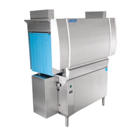
All operational relays use green LED-indicating lights
to verify proper operation. These relays are mounted
immediately to the right of the motor contactors.
Please refer to the illustration at right.
R1
R2
R3
R4
R5
LED
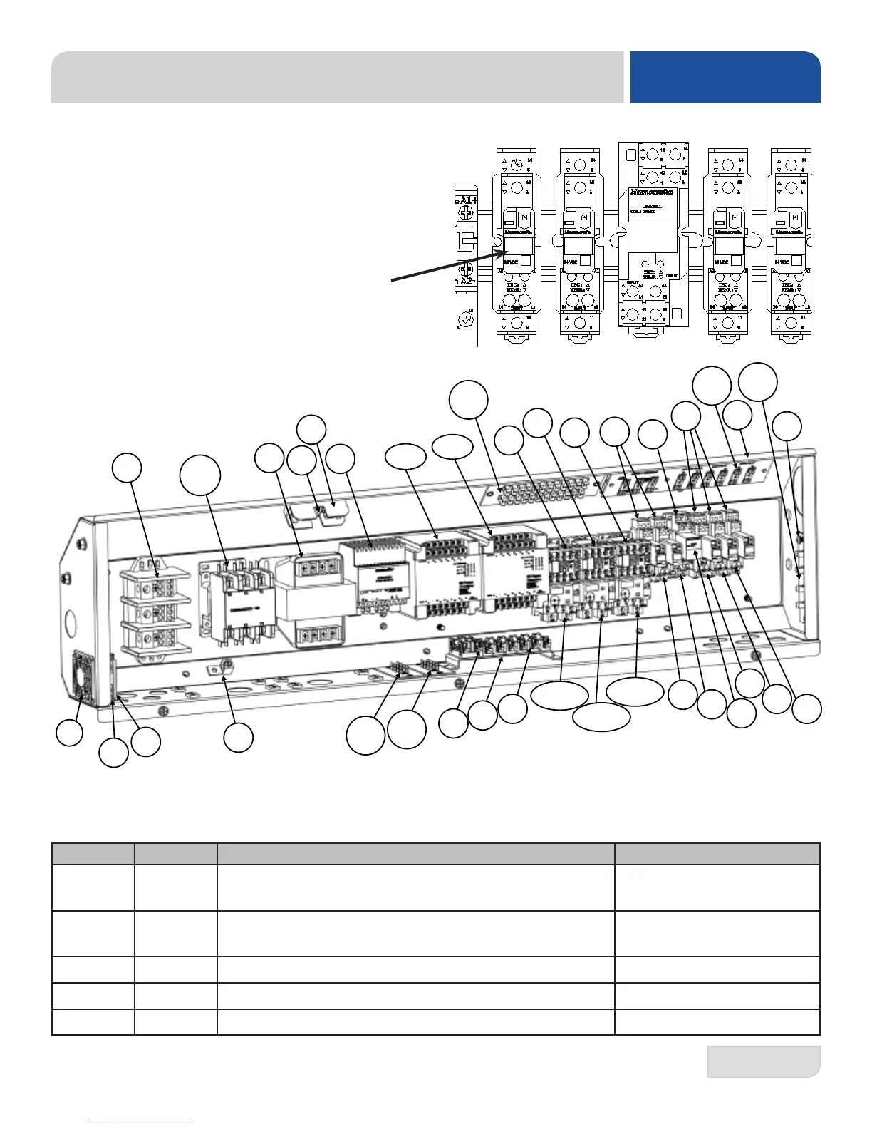
The illustration above depicts the components of a 66" electrically-heated unit with the booster heater option.
Component quantities and part numbers might vary for different units. Please refer to the notes within the parts list
on the next page to verify that the required part number is correct.
CONTROL BOX COMPONENTS
PARTS