17
07610-003-78-18-N
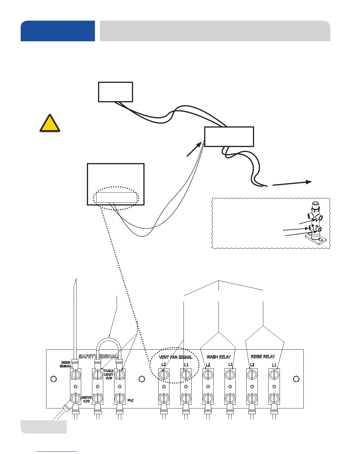
Electrical connection points for table limit switch, ventilation fan signal, and chemical dispensing systems.
Signal board is located in the main control box behind the lower dress panel.
Chemical Dispenser Tube Connection
Points to Rinse Injector:
P: Pressure Switch (1/4" NPT)
S: Sanitizer (1/8" NPT)
R: Rinse Aid (1/8" NPT)
INSTALLATION
EXTERNAL DEVICE WIRING
REMOVE THIS JUMPER
WIRE TO ALLOW FOR
TABLE LIMIT SWITCH
CONNECTIONS
VENT FAN
DETERGENT
DISPENSER
RINSE AID
& SANITIZER
ROM DOOR SWITCH
TABLE LIMIT
SWITCH
CONNECTION
CONNECTION POINTS FOR EXTERNAL DEVICES
115v AC Secondary Control Transformer Signal
NOTE:
Vent Fan wiring is
shown. All external
devices are wired
similarly.
Wiring Diagram
Terminal Board
Vent Fan
CREW
Dishmachine
Contactor
Supplied by Customer
To Circuit Breaker
Primary Load
Connect
wires to coil
of contactor
or relay.
Do NOT connect
primary load directly
to Terminal Board!
Terminal Board
!
CAUTION