File Version: 3.4 / JAKA Zu Series Hardware User Manual
4.
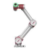
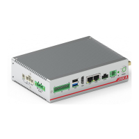
TIO supports 2 analog voltage input interfaces. The voltage input range is 0-10V, the analog voltage positive
terminal is connected to A1/A2, and the internal circuit of the negative terminal on the TIO board is grounded.
The wiring method: the external analog voltage positive electrode is connected to AIN1/AIN2 of TIO (white and
brown wire), and the internal circuit of the negative electrode on the TIO board is grounded. The V+ of external
device is connected to the 24V of TIO (red wire), and 0V of external device is connected to the GND of TIO
(gray wire).
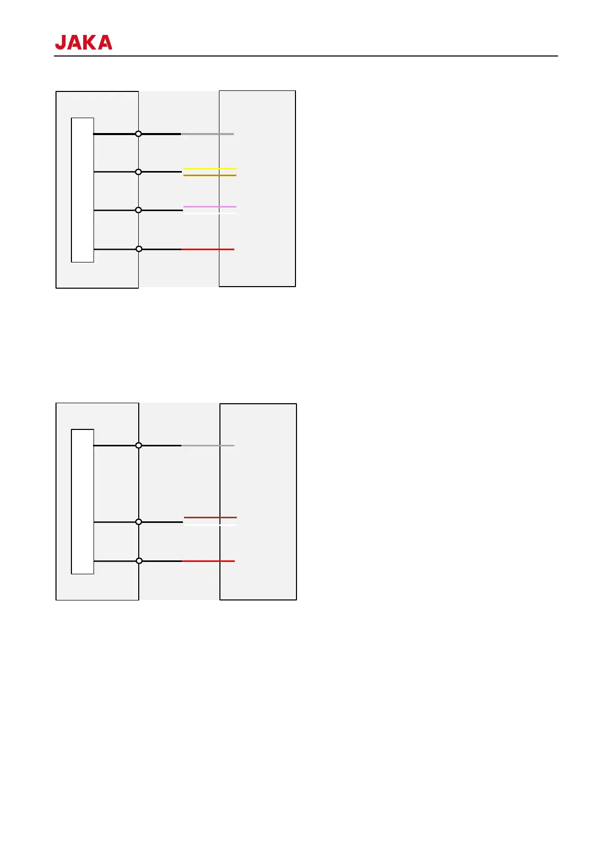
8.1.4
Use the robot connection cable provided by JAKA to connect the robot and the control cabinet. Before powering
on the robot, ensure that the connector is locked firmly. Before disconnecting the robot connection cable, the
robot must be powered off. The definition of the robot connection cable connector is shown as follows.
 Loading...