File Version: 3.4 / JAKA Zu Series Hardware User Manual
1. The robot has been tested according to international IEC standards for EletroMagnetic
Compatibility (EMC). Interference signals beyond the standard will cause abnormal behaviors of the
robot. Very high signal levels or excessive expoure can damage the robot permanently. JAKA will not
be held responsible for any damages caused by EMC problems.
2. The length of the I/O cable to connect the control cabinet and other machinery and factory
equipment must not be longer than 30 meters, unless the result of the extension test shows the
feasibility. Use shielding cables if necessary.
9.4
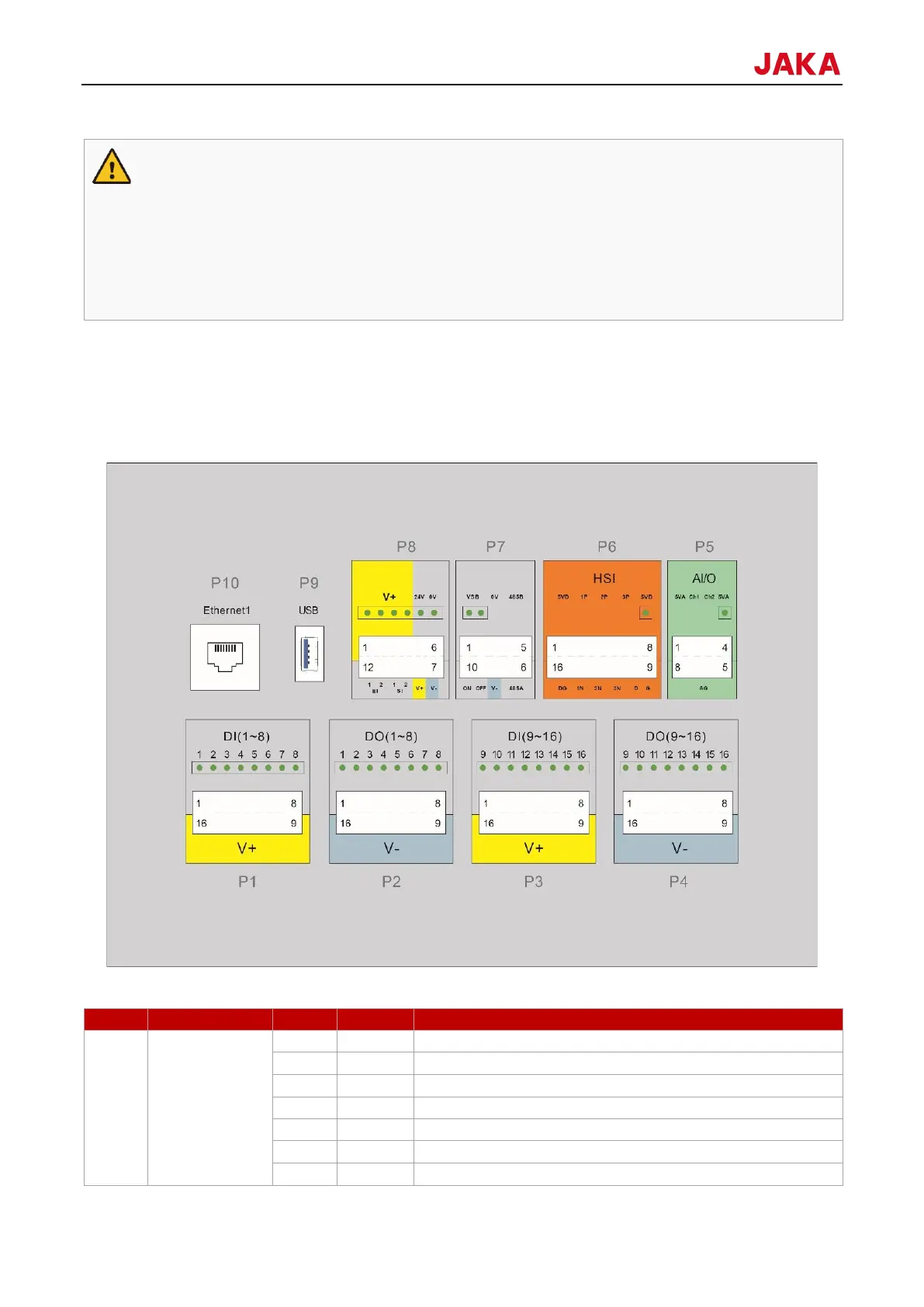
The front panel interface of the control cabinet is placed at the first layer after the control cabinet door is opened,
including 16 digital inputs (P1 and P3), 16 digital outputs (P2 and P4), two configurable analog interfaces (P5),
a set of high-speed interfaces (P6), remote switching and RS485 interfaces (P7), safety function interfaces (P8),
USB3.0 interface (P9) and Ethernet interface (P10), and the USB interface (P9) is retained for internal use. If
needed, contact the technical support personnel of JAKA.
9.4.1
DI (1-8)
8 digital inputs
Digital input 1, PNP type, active high
Digital input 2, PNP type, active high
Digital input 3, PNP type, active high
Digital input 4, PNP type, active high
Digital input 5, PNP type, active high
Digital input 6, PNP type, active high
Digital input 7, PNP type, active high