File Version: 3.4 / JAKA Zu Series Hardware User Manual
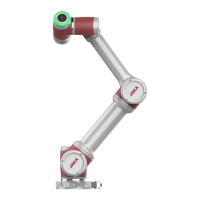
In most applications, to facilitate the safety-related operations, one or more additional emergency stop or
protective stop switch is needed. Wiring is shown in figure below. The V+ and V- can also be connected to the
external 24V power supply.
It is available to operate the robot without the control stick. In this case, you need to connect an additional
emergency stop device. You can use the EI interfaces on the front panel of the control cabinet to connect the
emergency stop switch to ensure safety.
1. If the control stick is detached or disconnected from the robot, the emergency stop button is no
longer active. You must remove the control stick from the vicinity of the robot.
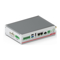
The protective stop function supports automatic recovery. The door switch is an application case of the protective
stop device. When the door is open, the robot stops.
9.4.5
With the 2 analog input and output interfaces (Ch1, Ch2), the mode can be configured:
1. Current signal input: 4-20mA;
24V
0V
P8
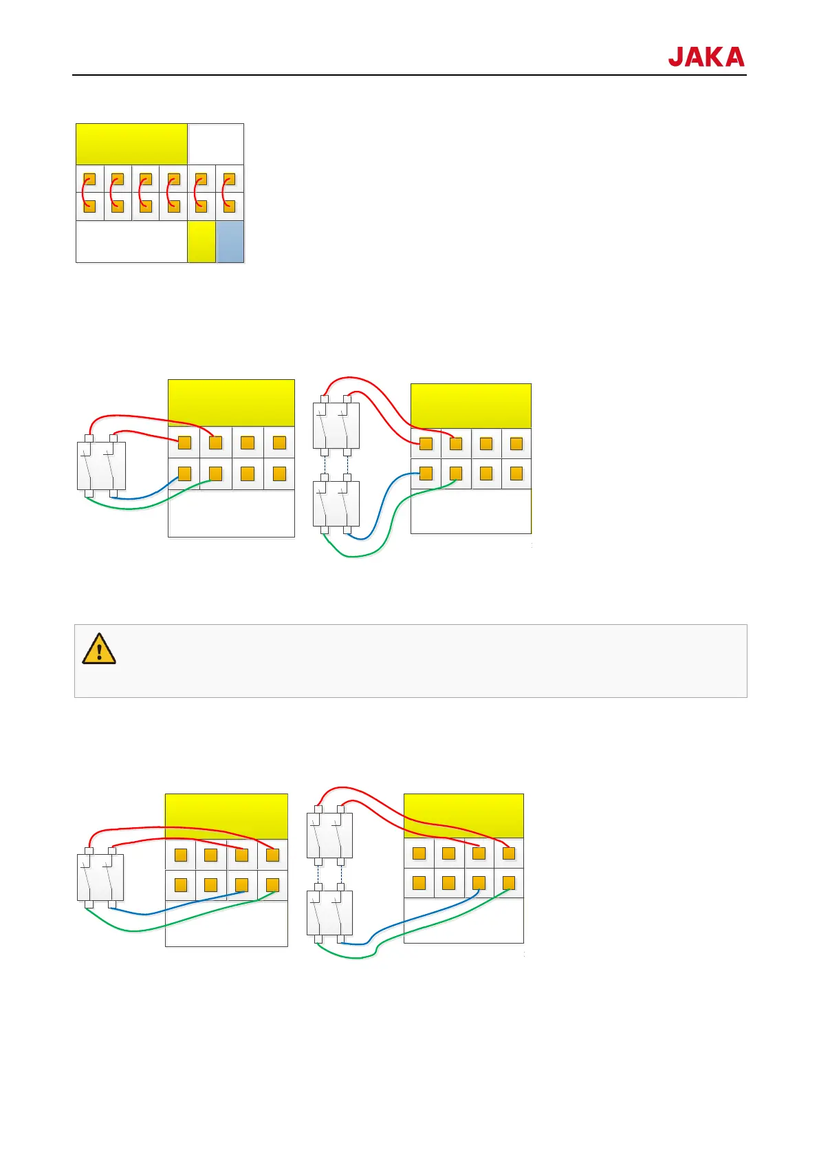
默认出厂安全配置
EI
1 2
SI
1 2
V+
V+ V-
0V
24V
P8
24V
0V
P8
紧急停止-单路开关
EI
1 2
SI
1 2
V+
V+ V-
0V
24V
P8
24V
0V
P8
紧急停止-多路开关
EI
1 2
SI
1 2
V+
V+ V-
0V
24V
P8
24V
0V
P8
防护停止-单路开关
EI
1 2
SI
1 2
V+
V+ V-
0V
24V
P8
24V
0V
P8
防护停止-多路开关
EI
1 2
SI
1 2
V+
V+ V-
0V
24V
P8