File Version: 3.4 / JAKA Zu Series Hardware User Manual
Analog input/output channel 2, configurable functions
Digital power 5V output, 100mA (max)
Differential signal 1 input positive terminal/encoder A+
Differential signal 1 input negative terminal/encoder A-
Differential signal 2 input positive terminal/encoder B+
Differential signal 2 input negative terminal/encoder B-
Differential signal 3 input positive terminal/encoder Z+
Differential signal 3 input negative terminal/encoder Z-
Digital power GND, isolated from the internal GND
Internal power 5V, 100mA (max), available for remote on/off
Internal GND (internal 24V, 12V, 5V reference GND)
Isolated power supply, input, and negative electrode, and
short jumper connected to the internal GND by default.
Remote Off signal input, active high (24V)
Remote On signal input, active high (24V)
Isolated power supply, input, and positive electrode, and
short jumper is connected to the internal 24V by default.
Internal 24V output positive electrode, 1.5A (MAX)
Internal 24V output negative electrode
Isolated power supply, input, and negative electrode, and
short jumper connected to the internal GND by default.
Protective stop function input 2; the default short jumper is
connected to V+
Protective stop function input 1; the default short jumper is
connected to V+
Emergency stop function input 2; the default short jumper is
connected to V+
Emergency stop function input 1; the default short jumper is
connected to V+
Internal debugging interface
Three-position enabling device network port
9.4.2
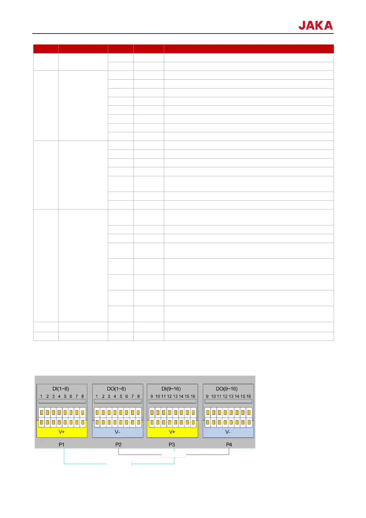
The following are the electrical specifications for the 24V digital I/O in the control cabinet. The design of the
digital I/O follows IEC 61131-2. The control cabinet supports the 16 digital inputs and outputs.