File Version: 3.4 / JAKA Zu Series Hardware User Manual
Digital I/O can be powered by the 24V power supply in the control cabinet and supports 1.5A peak output (the
output is stopped when overloading, the recommended output is less than or equal to 1A). If the user needs a
larger power output, it can power the V+ power supply with external “power”, which supports a maximum current
of 1.2A per channel. When using the external 24V power supply, you need to unplug the P8 interface 0V and
24V default jumper. 24V is the internal power supply +, and 0V is the internal GND. V+ is the positive electrode
of all digital I/O interfaces, and V- is the negative one. The default configuration is the connection to the internal
power supply.
9.4.2.1
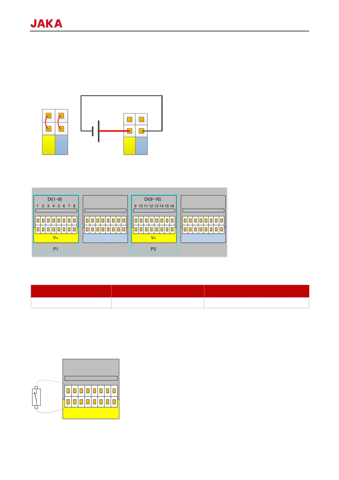
The control cabinet is equipped with a 16 PNP type digital inputs (active high) (DI1-DI16), which supports
isolated signal input. The level signal meets the standard of IEC61131-2 (Type1/2/3) and is used to detect the
input signal voltage level state.
V+ supports external 10-35V power input, and the internal 24V power supply is connected by default.
Users can also short it to V+ through buttons or switches.
Wiring for different types of input signals are different. The specific connection method is as follows (take DI1
as an example, same as DI2-DI16):
1.