File Version: 3.4 / JAKA Zu Series Hardware User Manual
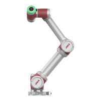
When the dry contact is input, one wire is connected to V+, and the other is connected to the DI specified
channel. When the circuit is connected (as shown in the figure, the switch or relay is turned on), the
corresponding indicator on the panel is on. The corresponding indicator will light on in the JAKA Zu App at the
same time.
2.
The PNP input wiring method is shown in figure below (take DI1 as an example, same as DI2-DI16), with the
power wire V+ connected to the terminal V+, the OUT signal wire to the specified DI channel, and the 0V wire
to the panel V-. When a signal is triggered, the corresponding indicator light on the panel is on. The
corresponding indicator will light on in the JAKA Zu App at the same time.
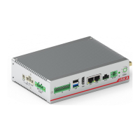
9.4.2.2
The control cabinet is equipped with 16 digital PNP signal outputs (DO1-DO16), which supports isolated signal
output.
High-side output is used internally, and its maximum continuous current can reach 1A. But when the V+ shorts
by default to the internal 24V power supply, the 24V power current is limited to 1.5A.
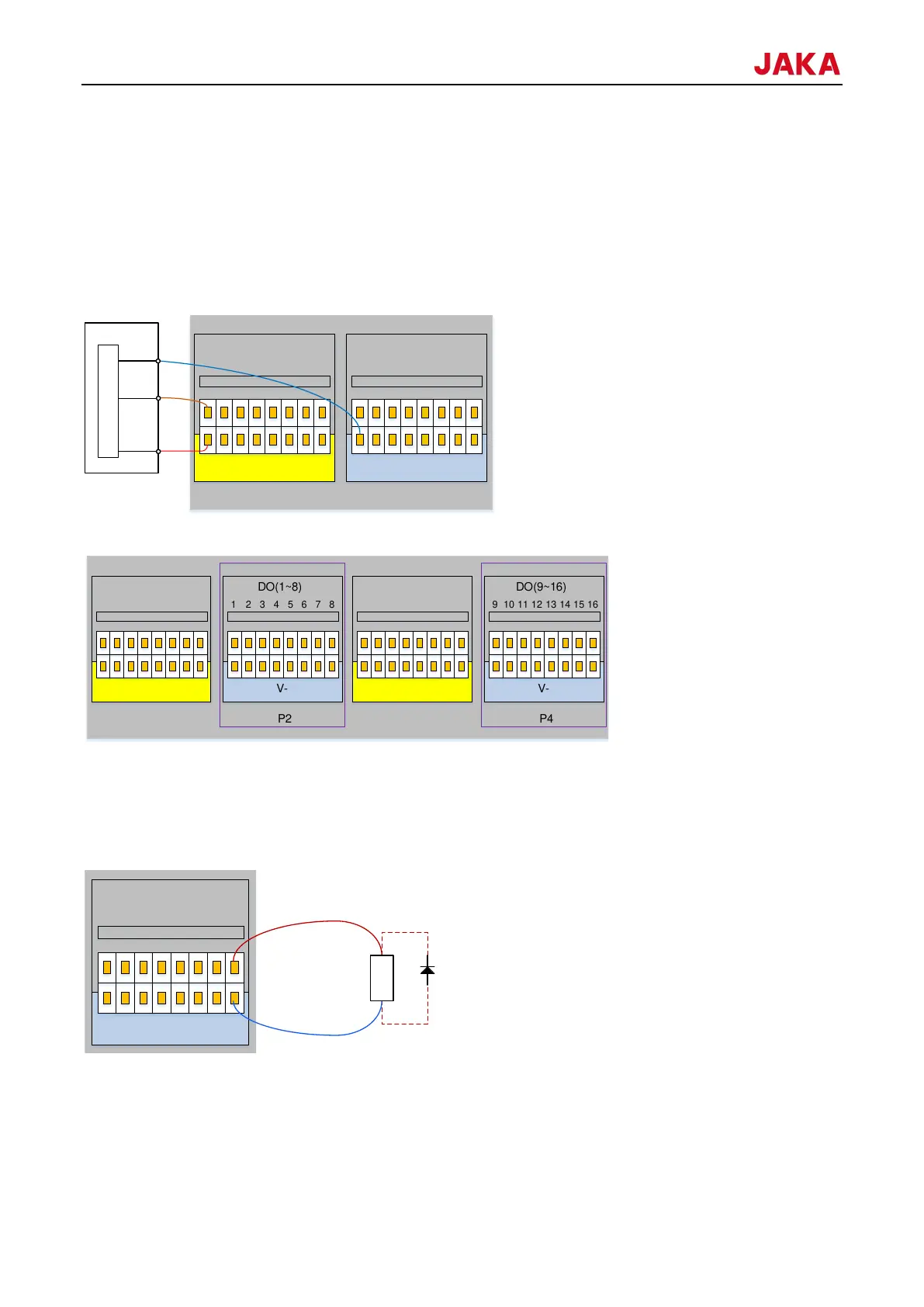
The wiring of digital output wiring is shown in the figure below (take DO8 as an example, same as others):
Digital outputs can be controlled through the DO function in the App. The current of one DO is 1A, the total
current cannot exceed 1.5A.
Note: It is recommended to use protective diodes (such as the relay, electromagnet, and DC motor) for inductive
load.
 Loading...