File Version: 3.4 / JAKA Zu Series Hardware User Manual
9.4.3
In order to configure the safety functions of the robot, the digital I/O interfaces P1 to P4 on the control cabinet
can be set up as dedicated safety I/O. The electrical specifications refer to 9.4.2 Digital I/O Interfaces. Safety
I/O is designed with dual-redundancy, where a failure in one channel will not compromise the safety functions.
Therefore, when wiring, both paired safety I/Os should be connected simultaneously. For example, when
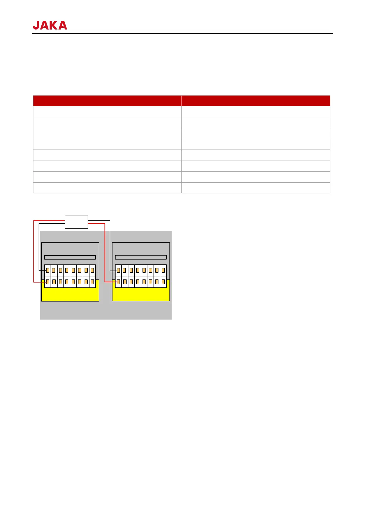
connecting DI1, DI9 must be connected simultaneously. The pairing relationship for safety I/O is as follows:
For example, when you configuring the three-position enabling (3PE) function (see 1.7.1 JAKA App Software
User Manual), the wiring is as follows (take DI1&DI9 as an example, same as others):
The wiring for other safety functions is the same as that for the three-position enabling function.
9.4.4
The control cabinet has two types safety interfaces, and users can configure emergency stop and protective
stop functions by them. EI and SI stand for emergency stop and protective stop respectively, both of which are
redundant. When either signal is active, the corresponding safety function can be enabled. Emergency stop and
safety stop are both designed with dual-channel configurations. If you intend to use external safety devices,
please select devices that support dual-channel design.
Users can access security doors, security light curtains, sensors, etc., according to actual safety requirements.
The robot can be operated without any additional safety equipment. The EI1-2 and SI1-2 is short connected to
the V+, while the V+ shorts to 24V. The V- shorts to 0V, indicating that the 24V power supply is internally provided
by the control cabinet.