Page 19
ENGLISH
Jandy
®
, JXi
™
Gas-Fired Pool & Spa Heater
|
Installation & Operation Manual
Section 6. Water Connections
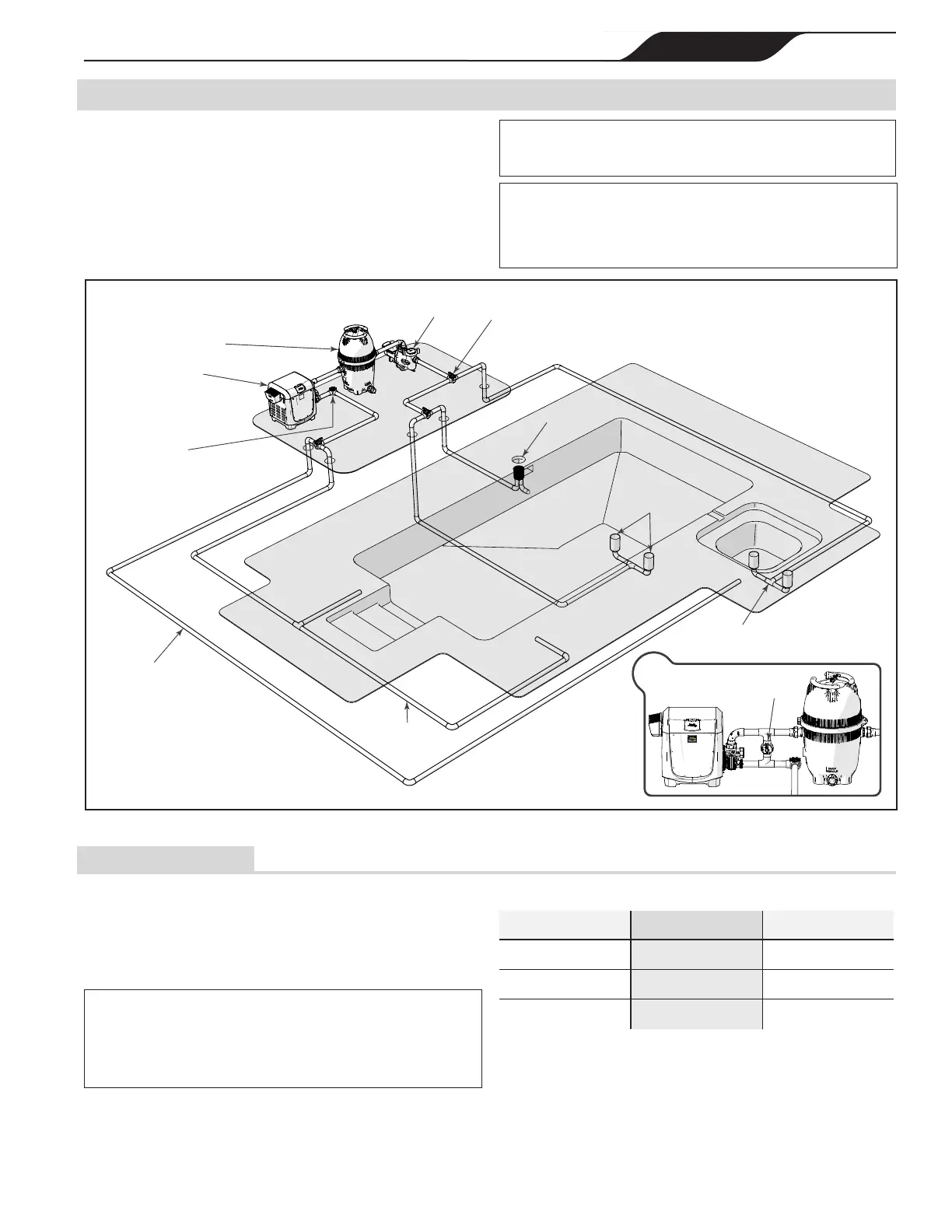
Install pool system components with connections as
illustrated in Figure 10. Any conguration other than
as illustrated in Figure 10 can affect the operation of
the water pressure switch. Locating the heater above or
below the pool water surface can also affect operation of
the water pressure switch.
NOTE: When pool equipment is located below the pool surface,
Zodiac Pool Systems, Inc. is not responsible for any large scale
waterloss,oodingordamagecausedbyaleak.
CAUTION
The pool equipment must be protected from back-siphoning of wa-
ter. If there is any chance of back-siphoning, provide a check valve
betweenthepoolandthelterpumpinlet.
Figure 10. Typical Water Piping Conguration
MAIN DRAINS
(Suction Outlet)
MANUAL BYPASS VALVE
HEATER
FILTER
CHECK VALVE
(Always install a corrosion resistant check
valve when any sanitation equipment,
including erosion feeders and salt
chlorination systems are installed,
see section 5.4
for more details)
PUMP
POOL/SPA
3 WAY VALVE
SPA DRAIN
(Suction Outlet)
SKIMMER
SPA RETURN
POOL
RETURN
a.
a.
MANUAL BY-PASS DETAIL:
USE WHEN FILTRATION RATE
EXCEEDS 100 GPM
6.1 Pump Sizing
For ASME heater models JXi400NC, JXi400PC, JXi260NC and JXi260PC please go to “Appendix A. ASME® Header” on page 49.
All JXi heaters utilize an internal bypass mechanism and
thermal regulator valve (TRV) to accommodate ow rates
delivered to the heater from a minimum of 30 gallons per
minute (gpm) to a maximum ow of 100 gpm.
CAUTION
The system water pump must be capable of providing no less than
30gpmofowthroughtheheater.Flowratesatlessthan30gpm
may cause nuisance operation causing damage to the heater or
causing the heater to turn off.
MODEL MIN GPM (LPM) MAX GPM (LPM)
JXI 200
30 (114) 100 (379)
JXI 260
30 (114) 100 (379)
JXI 400
30 (114) 100 (379)
Table 4. Recommended Flow Rate Adjustment
 Loading...