Page 22
ENGLISH
Jandy
®
, JXi
™
Gas-Fired Pool & Spa Heater
|
Installation & Operation Manual
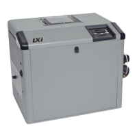
Sweep ElbowUnion Nut
Union Nut
Union Tailpiece
Union Tailpiece
Cut Pipe
Cut Pipe
O-Ring
O-Ring
O-Ring
Drain Cap
Top Inlet Manifold Orifice
Side Inlet Manifold Orifice
Manifold Outlet
Figure 13. Inlet Piping
• Align Tailpiece and manifold orice.
• Secure to manifold with union nut hand tight only. Do
not overtighten. Do not use pipe joint or thread tape.
• If using the sweep elbow. Use approved NSF
adhesive to glue the sweep elbow onto the cut pipe.
• Repeat the above steps for the manifold outlet. Again
paying special care to ensure proper seating of the
union tailpiece o-ring.
• Install the union nut and drain cap with o-ring at the
unused inlet on the heater manifold. Be sure that the
o-ring is properly seated. Secure hand tight only. Do
not overtighten. Do not use pipe joint or thread tape.
• Return all valves to their operating positions.
• Restore power to the heater at the breaker.
• Turn on pump and inspect carefully for leaks.
• Restore main gas supply.
• Start the system and check for proper ow.
• Return heater to normal operation.
WARNING
To avoid an electrical shock hazard, which can result in serious
injury or death, ensure that all electrical power to the system is
turned off before approaching, inspecting or troubleshooting any
leaking valves or plumbing that may have caused other electrical
devices in the surrounding area to get wet.
Followallltermanufacturer’sinstructions.Never
attempt to assemble, disassemble or adjust the
lterwhenthereispressurizedairinthesystem.
Starting the pump while there is any pressurized
airinthesystemcancausethelterlidtobe
blown off, which can cause death, serious
personal injury or property damage.
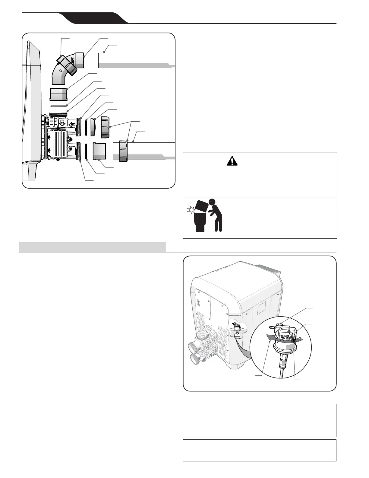
6.3 Water Pressure Switch Adjustment.
The water pressure switch is inside the heater jacket on
the water connection side See Section 1.8, item “f”.
The switch is preset at the factory. The pressure switch
setting must be adjusted If the heater is installed:
• Below the surface level of the pool
• More than two feet above the pool level
• Where the pressure is measured at 1 psi or greater
with the lter pump off
Location of the heater above or below the pool water surface
can also affect the operation of the switch. The factory
installed switch can accommodate elevations of 6 feet above
the pool water surface or 11 feet below the pool water surface.
If the heater water connections are outside this range Consult
your local Zodiac
®
representative for recommendations.
• Set the heater control to “OFF”.
• Remove seven screws securing the side panel to the
heater body.
• Remove the side panel to gain access to the water
pressure switch. See Figure 14.
• Turn the lter pump on and conrm that the pressure
switch closes with a voltmeter.
• If the switch does not close, check that all valves are
open to the heater and that there are no restrictions in
the line. You may also need to conrm ow rate from
your pump as outlined in Section 5.1.
Pressure
Switch
Rotate clockwise with fingers
until heater turns off. Then rotate
couterclockwise 1/4 turn to set.
Leads
Adjustment
Sprocket
Figure 14. Water Pressure Switch Adjustment
CAUTION
The water pressure switch should be adjusted to turn the heater off
whenthepumpisoff.Settingtheswitchtocloseattoolowowcan
damage the appliance. Adjust the switch to turn the heater off, not on.
NOTE: It is recommended that a Pressure Release Valve (PRV) be
installed prior to taking any of the steps below. Please see Section
5.5 for details.
 Loading...