Page 27
ENGLISH
Jandy
®
, JXi
™
Gas-Fired Pool & Spa Heater
|
Installation & Operation Manual
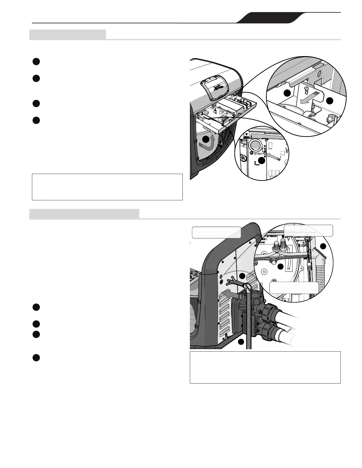
7.1 Service Access
• Remove the four screws holding the front heater
panel in place to expose the raceway.
Locate the raceway lock release on the interior of the
heater raceway.
b
Using a screwdriver or comparable tool; press into the
raceway release orice until the raceway latch releases, and
the raceway swings free.
Secure the raceway in place by lifting until the locking
latch engages.
d
Push the tab on the locking latch to the
left to release.
• Press raceway down and back until an audible click
indicates that it is latched in position.
• Replace heater front panel.
Tech Tip: For greater access remove the top panel by remov-
ing the 4 black screws on the outside of the heater.
NOTE: Beforetheracewaycanberotatedforthersttimea
shipping zip tie must be cut. This zip tie is threaded at the raceway
release point see item (a). While cutting this zip tie be sure not to
damage or abrade any of the wires.
7.2 Main Wiring Connections
The main wiring connections should be available
externally to the heater at the time it is unpacked. Use
exible conduit to run the main power lines from the
power source to the heater connections. No external
junction box is required.
• Ensure that all electrical power is shut off to the
heater at the breaker.
• Ensure that the lter pump is off and will stay off for
the remainder of the procedure.
• Follow applicable service access instructions
from Section 6.1.
Run conduit and power lines from main power source to
the heater side panel.
b
Make wire connections via wire nuts.
Push wire connections through the knockout into the heater
body. Be careful not to damage or abrade any wiring during
this procedure.
d
Secure the conduit to the heater body panel at the knockout
using a suitable conduit connector or elbow.
Connect Power Source
to Heater Leads
Connect Conduit at Port
in Side Panel
Heater Interior
(access from front panel)
b
a
c
d
NOTE: If the heater is converted to accept 120V, the “Hot” wire
of the 120V power supply has to be connected to the black wire
(ACH1) on the power distribution board and the “Neutral” wire of the
120V power supply has to be connected to the red wire (ACN1) of
the power distribution board. Please see Figure 16 for details.
d
b
c
a
H0495500_REVA
 Loading...