Page 21
ENGLISH
Jandy
®
, JXi
™
Gas-Fired Pool & Spa Heater
|
Installation & Operation Manual
6.2.1 Reversing Plumbing Connections
The JXi heater is shipped with the manifold on the right
side by default. If necessary the water connections can
be orientated to the left side by rotating the top panel
of the appliance.
NOTE: The electrical raceway, transformer, PIB, Ignition control
and voltage selector board are all accessed through the default front
panel. Special considerations should be made for service clearance,
see Figure 2,beforethenallocationandorientationoftheappli-
ance is determined.
• Turn off all power to the heater at the breaker.
• Ensure that the pump is off and will remain off for
the duration of the procedure.
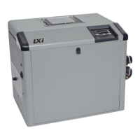
Remove the four black screws securing the heater top
panel to the heater body.
Lift the heater top panel. Be careful not to damage or apply
undue stress to the user interface wiring.
Rotate the heater top panel 180°.
• Place the heater top panel on the heater body.
• Secure with the four screws removed in step “a”.
• Restore power to the heater.
• Return the heater to normal operation.
6.2.2 Water Inlet Piping
For ASME heater models JXi400NC, JXi400PC, JXi260NC and JXi260PC please go to “Appendix A. ASME® Header” on page 49.
There are two options for water inlet connections on
the JXi. Both congurations use the same water outlet
to return heated water to the pool. Be sure to check
ow rates as outlined in Section 5.1 and if necessary
make provisions for and ensure sufcient space for the
installation of a manual bypass valve as outlined in
Section 5.1.1.
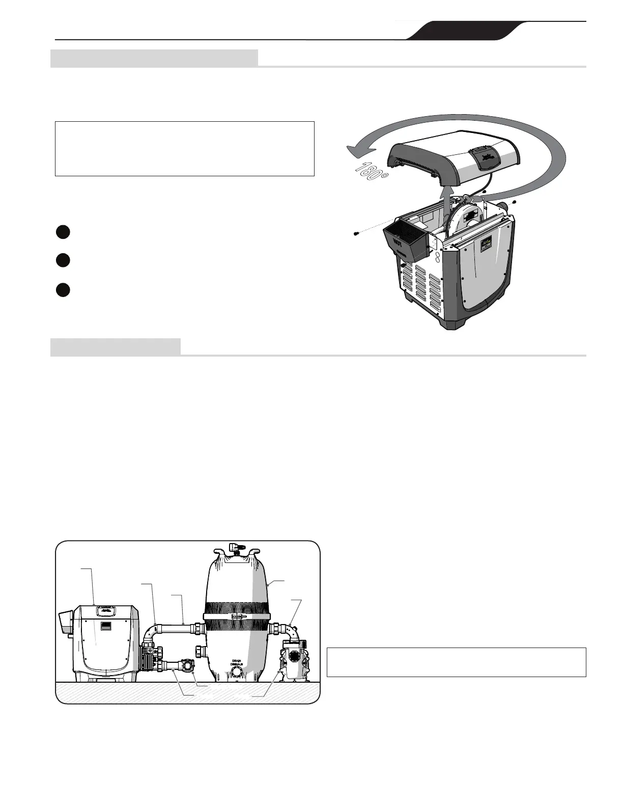
The top inlet is intended for use with the
Jandy Versa Plumb
®
sweep elbow. Plumbing in
this conguration can increase hydraulic efciency
particularly when used in a system with other
Versa Plumb compatible, Jandy Equipment.
See Figure 12.
Sweep
Elbow
Inlet
Filter
Outlet
Check Valve
Pump
Heater
Sweep
Elbow
Figure 12. Versa Plumb Heater Inlet
The sweep elbow also provides the advantage of its
exclusive interface with the Zodiac AquaLink
®
RS
temperature sensor.
The side inlet is positioned at a 10 1/8 in (255.7 cm)
center height providing an ideal height for replacement
unit or new construction plumbing.
• Turn off all power to the heater at the breaker.
• Turn off main gas supply to heater.
• Ensure that the pump is off and will remain off for
the duration of the procedure.
• Do a dry t test of cut pipe lengths in order to ensure
proper seating of the union tailpiece and o-ring. Make
adjustments to pipe length or positioning as needed.
• Clean all adhesion surfaces with an appropriate NSF
®
approved all purpose cleaner/primer.
• Slide the union nut onto the cut pipe length. or sweep
elbow. Ensure proper nut orientation with threads
directed towards the heater manifold. See Figure 13.
• Use approved NSF adhesive to glue the tailpiece onto
the cut pipe, or sweep elbow.
NOTE: Zodiac Pool Systems, Inc. recommends Weld-On® 724TM
PVC to CPVC Cement to glue Schedule 40 PVC.
1
8
0
°
 Loading...