Page 24
ENGLISH
Jandy
®
, JXi
™
Gas-Fired Pool & Spa Heater
|
Installation & Operation Manual
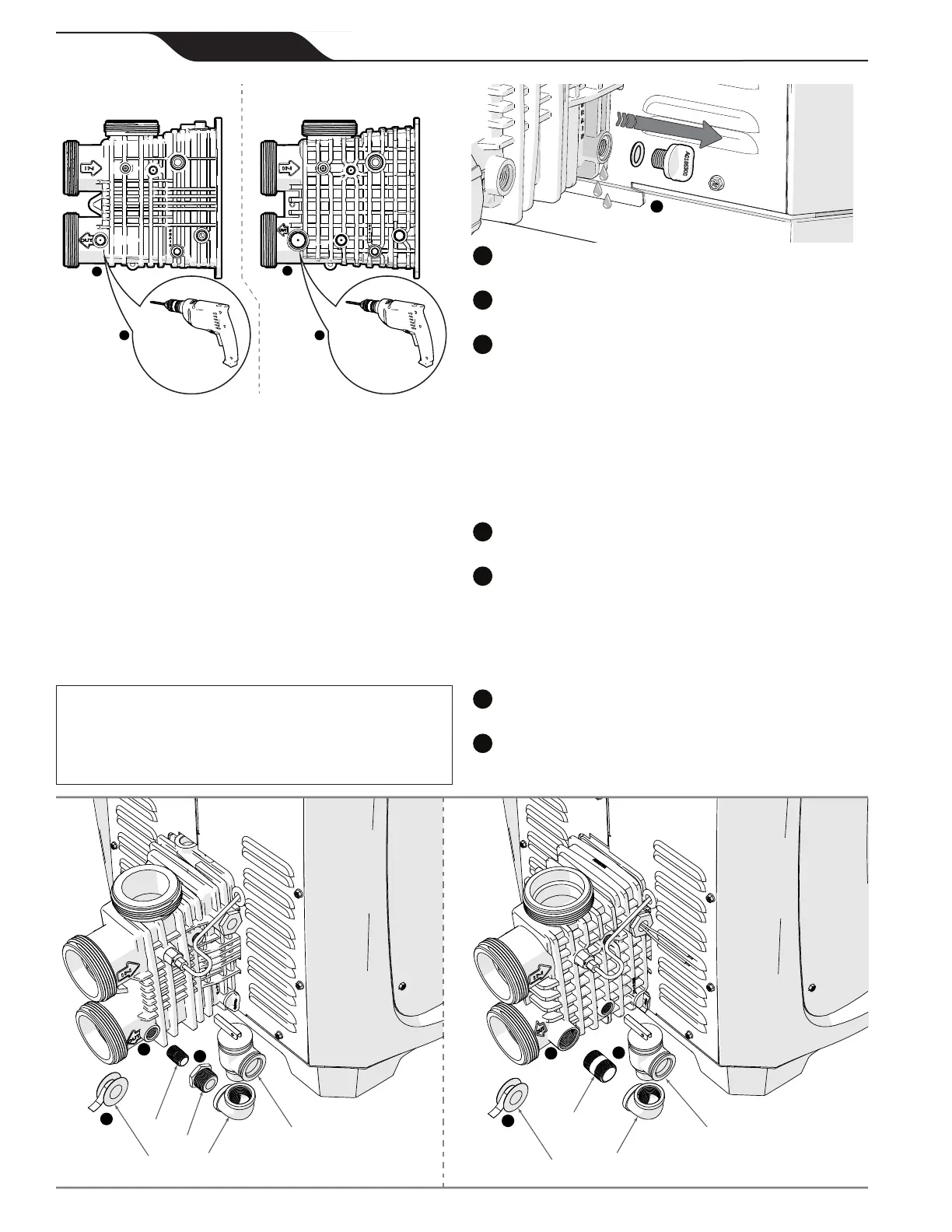
Figure 15. Identifying Header Design
b
b
Drill Using
a 1/4 in Bit
Drill Using
a 3/8 in Bit
Heater Revision “K” and Earlier Heater Revision “L” and Later
Header Type “A” Header Type “B”
cc
TIP: Drilling a 1/8 in diameter hole first will help prevent thread damage.
• Turn off the electrical power to the heater.
• Turn off the main gas supply to the heater.
• If the heater has been operating, ensure you allow
enough time for remaining water in the heat
exchanger to cool down before beginning. It is
recommended that protective gloves be worn during
the entire procedure.
• Make sure the lter pump is off and will remain off
for the duration of the installation procedure.
• If the heater is below the surface level of the water in
the pool or spa, close all shut-off valves between the
heater and the pool.
CAUTION
UsePTFE(Teon)tapeonlyonthethreadsofthepipenippleattach-
ment to the plastic header.
Do not use pipe compound or pipe dope
on threads or any part that comes into contact with the plastic header.
These compounds may damage the header over a period of time.
a
Remove drain plug from header and allow all water to
drain from heat exchanger.
b
Locate the threaded boss on the outlet port of the header,
and nd the dimple at the center.
Use the dimple to center the drill bit.
For header type A: Drill a 1/4 in (6.4 mm) diameter hole
through the boss.
For header type B: Drill a 3/8 in (9.5 mm) diameter hole
through the boss.
Take care not to damage the plastic threads.
TIP: Drilling a 1/8 in (3 mm) diameter hole first will help
prevent thread damage.
d
Each male connection should be rst wrapped in 5-6 turns
of PTFE (Teon) tape.
For header type A: Assemble the 3/8 in threaded nipple,
reducing bushing, elbow and pressure relief valve. Make sure
to get a sung t. Do not overtighten.
For header type B: Assemble the 3/4 in threaded nipple, elbow
and pressure relief valve. Make sure to get a sung t. Do not
overtighten.
f
Install the pressure relief valve assembly at the heater
header. Make sure to get a sung t. Do not overtighten.
The nal orientation of the pressure relief valve should be
vertically aligned with the discharge opening facing away from
the heater header.
e
e
f
f
d
d
3
1
6
6
2
1
4
55
Header Type “A” Header Type “B”
 Loading...