VT X A12 | Rigging Manual
16
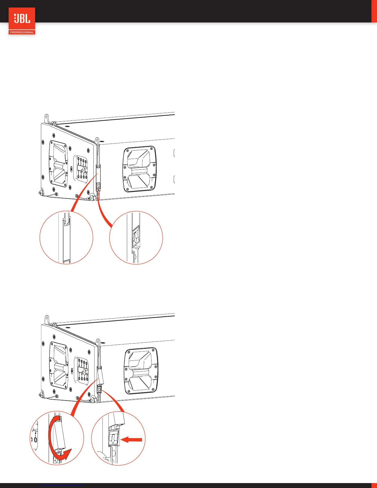
7.2 - VTX A12 - ANGLE-LOCK MECHANISM
VTX A12 includes an innovative Angle-Lock mechanism that automatically engages when the cabinets are suspended and reach the
desired angle position. The Angle-Lock mechanism consists of two main parts, the RED LOCKING LEVER and the black RELEASE
BUTTON.
The system is locked when the RED locking lever is recessed
into the cabinet. When the cabinets are suspended, a sequen-
tial locking sound is audible that indicates that the system
reached the final position and is locked. The system will remain
locked until the Angle-Lock mechanism has been released.
LOCKED POSITION
When it’s time to de-rig the system, the Angle-Lock mechanism
is released so that the cabinets can collapse again and be set
on the VTX A12 VT at 10-degrees. Press the release button to
unlock the mechanism.
When the button is pressed, the RED locking lever is released
and moves to the unlocked position. The RED locking lever is
spring loaded and will maintain its position until the user man-
ually changes the mode. The Angle-Locks are set to the unlock
position until the cabinets are attached to the VTX A12 VT and
collapsed all the way to 10-degrees.
NOTE: The RED Angle-Lock levers are used to secure the angle
position and prevent the cabinets from taking a different angle
when cabinets are deployed in an array. The RED Angle-Lock
lever is not load-bearing and the system is safe even if they are
accidentally left in the unlocked position.
UNLOCKED POSITION
LOCKING LEVER
RELEASE BUTTON
 Loading...