VT X A12 | Rigging Manual
34
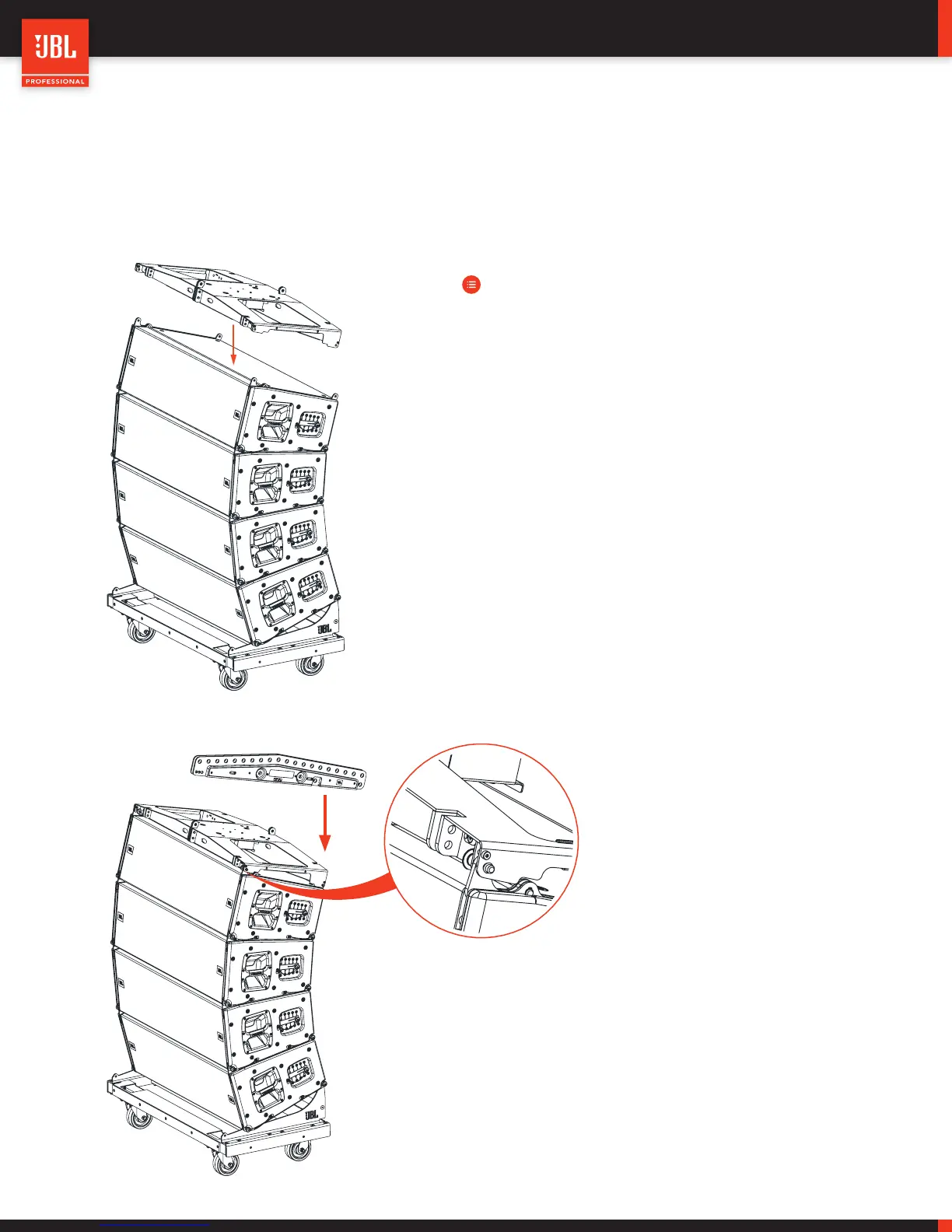
9.10 - ATTACHING THE ARRAY FRAME
The VTX A12 Array Frame was designed to be both lightweight and easy to handle whether it is transported on top of arrays or
separately in a case. Since the Extension Bar was designed to attach and travel on the Array Frame, these instructions assume this
use case, although transportation together is recommended, it is not required.
STEPS:
• To make it easier to attach, separate the Array Frame from
the Extension Bar.
• Ensure that the top cabinet is set to the correct angle and
ensure that the Array Frame is oriented in the proper di-
rection. Lift the frame over the top A12 cabinet on the cart
and place it resting on the 4 QRP attachment points on the
top of the cabinet.
• Remove the QRP’s from their storage positions and place
each one into its respective attachment position. The QRP’s
should be attached from the inside of the Array Frame.
• Once the Array Frame is secured to the top of the cabinet,
the Extension Bar can be attached. Confirm its correct ori-
entation by consulting the LAC and ensure that the correct
A, B, or C position is attached using both of the included
large-gauge QRP’s.
 Loading...