VT X A12 | Rigging Manual
17
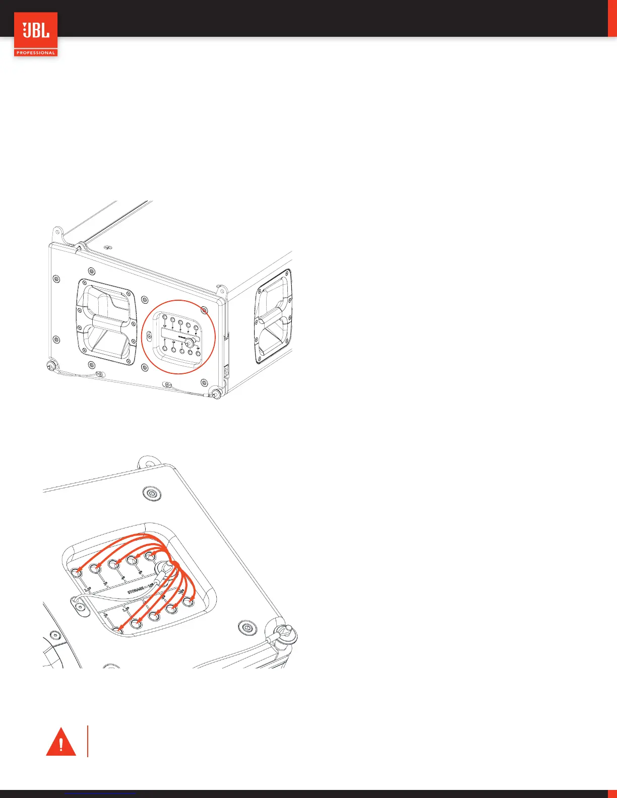
7.3 - VTX A12 - ANGLE SELECTION
Each VTX A12 includes two Angle Selection panels (one on each side) that are used for selecting the cabinet-to-cabinet splay angle.
The options are marked in degrees and the panel allows for 11 unique positions ranging from 0.25-degrees to 10-degrees.
VTX A12 ANGLE OPTIONS: 0.25°, 0.5°, 1°, 1.5°, 2°, 2.5°, 3°, 4°, 6°, 8°, 10°
A dedicated quick release pin is available for selecting the an-
gles. Angles are selected when the VTX A12 cabinets are set
on the VTX A12 VT and resting on the ground. When the sys-
tem is on the ground, the quick release pins are not under load
and can freely move to the desired position.
During transportation, VTX A12 cabinets should always be set
to 10-degrees. This ensures that the rigging system is locked,
preventing any accidental movement or angle selection.
To select an angle, remove the quick release pins from the stor-
age position (10°) and set them to the desired position. After
the array has been lifted from the ground, the weight is shifted
to the quick release pins and selecting an angle is no longer an
option.
CAUTION: All quick release pins on a VTX A12 system must always be placed in a hole. Do not suspend
VTX A12 system if pins are freely hanging
 Loading...