VT X A12 | Rigging Manual
37
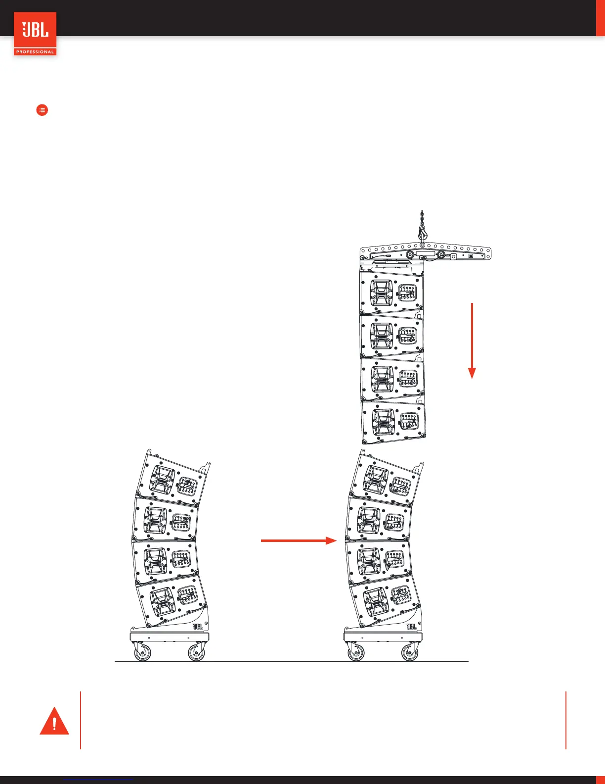
STEPS:
• Raise the suspended cluster of VTX A12 cabinets and align the next cart of VTX A12 cabinets on a Vertical Transporter
underneath the suspended cluster.
• Once the two clusters are aligned, carefully lower the suspended cluster until the front attachment points are nearly touch-
ing the front attachment points of the stacked cluster. Ensure that the attachment points are aligned and then lower the
suspended cluster until the front attachment points come together . Insert the QRP’s and attach the suspended cluster
to the stacked cluster.
10.3 - ATTACH THE NEXT STACK
CAUTION:
• Always ensure each cabinet is pinned to the same angle on each side of the enclosure
• The topmost cabinet in each array should be pinned in accordance with the Array Frame and Extension Bar po-
sitioning instructions in section 9.6.
 Loading...