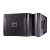
VT X A12 | Rigging Manual
28
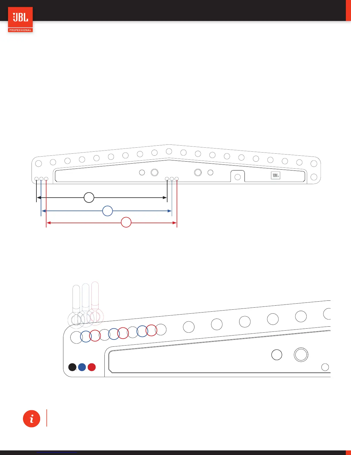
9.4 - EXTENSION BAR ATTACHMENT OPTIONS
The VTX A12 AF Extension Bar includes 3 x attachment positions for connecting to the Array Frame. The 3 x positions allow for ad-
ditional aiming resolution when an array is suspended from a single point. In single-point applications, the array aiming is determined
by the shackle position on the Extension Bar. The VTX A12 Extension Bar includes 20 x shackle positions, which are spaced apart
by 51mm (2”) to maintain the structural integrity of the bar. Even at 51mm apart, the spacing is not frequent enough for precise
sub-degree aiming, and a shackle position is needed between two holes. The 3 attachment positions (A, B and C) allow for 2 addi-
tional shackle positions between holes and increases the total shackle positions to 60.
A
B
C
1
2
3
4
5
6
7
8
9
10 11
12
13
14
15
16
17
18
19
20
The example below shows how the real and “virtual” positions are spaced across the extension bar.
A
B
C
B
C
A
B
C
A
TIP: Refer to JBL’s Line Array Calculator software to determine the best possible shackle position and at-
tachment combination to achieve the required array angle.
 Loading...