VT X A12 | Rigging Manual
30
9.5 - EXTENSION BAR STORAGE POSITIONS
The Extension Bar can be secured to the top of the A12 Array Frame for transportation and storage when not in use. Guides have
been built into the top of the A12 Array Frame and the storage position of the Extension Bar in order to facilitate quicker attach-
ment, and once the Extension Bar is properly in place to be stored, the attached QRP’s from the Extension Bar can be used to
secure the two pieces together. Each A12 Array Frame can facilitate up to 2 x A12 Extension Bars.
STEPS:
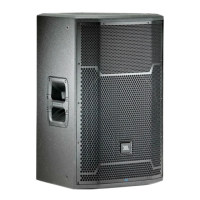
• Place the Extension Bar longways (Left to Right) across
the top of the Array Frame, ensuring that the label side
of the Extension Bar is pointed upwards.
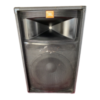
• Slide the Extension Bar into place on top of the Array
Frame, ensuring that the two alignment locator’s from
the bottom side of the Extension Bar locate themselves
into the storage position alignment cutouts in the top
of the Array Frame.
• Use the two included Quick Release Pins to secure the
Extension Bar to the Array Frame.
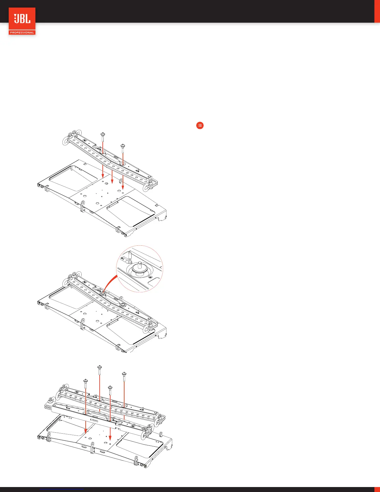
DUAL EXTENSION BARS
To store a second Extension Bar, simply repeat the above
steps and secure the second Extension Bar to the front
part of the top of the Array Frame.
 Loading...