VT X A12 | Rigging Manual
36
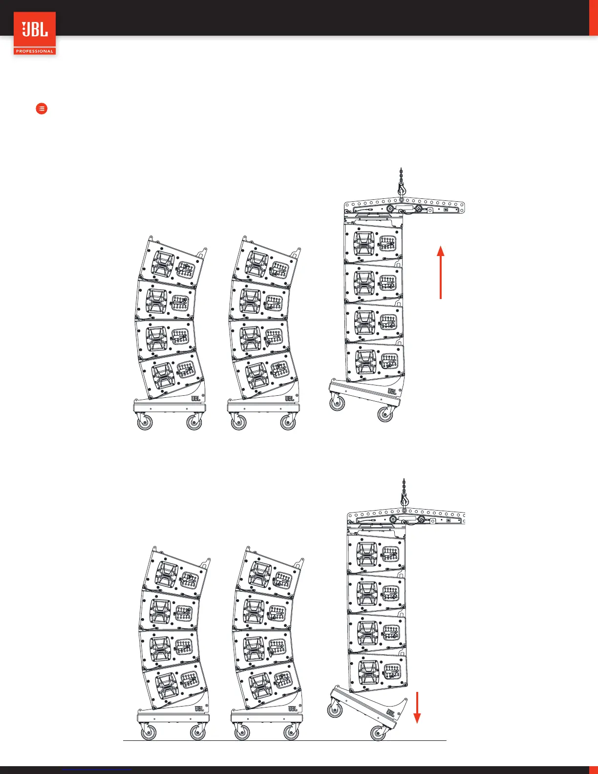
STEPS:
• Ensure that all red suspension Locking Levers are in the locked position, and then engage the hoist to lift the array off the
ground. As the hoist lifts, each cabinet will expand to the correct inter-enclosure angle, and the sound of pins sliding past
locking points will be heard. Each cabinet will stop expanding when it reaches the correct inter-enclosure angle.
• When all cabinets are set, and the array is suspended a short distance off the ground, disconnect the Vertical Transporter
(VT) by removing the two rear QRP’s followed by the front pins. The array should not be so high in the air that the Vertical
Transporter is swinging freely.
10.2 - SUSPEND THE FIRST STACK
 Loading...