NT-2000 REF Manual
Installation
7-8
7.3.2. Connector Pin Assignments and Connections (
continued
–
2/8
)
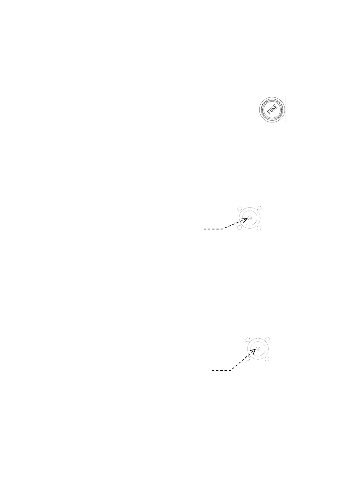
③ Fuse Holder
Figure 7-8 Fuse Holder
A 3–ampere (3A) cartridge fuse ( 5.2X20 mm, slow–blow
type) is inserted in the holder.
Reversing the power cable polarity causes the fuse to blow.
< WARNING >
AN INCORRECTLY RATED FUSE OR INCORRECT TYPE FUSE WILL
BLOW AT POWER–UP OR WILL NOT PROTECT THE EQUIPMENT IN THE
REMOTE EVENT OF A TROUBLE OVERLOADING ITS POWER SUPPLY.
④ Antenna Receptacle (BNC) for Active Antenna ANT–2000
Figure 7-9 Antenna Connector for ANT–2000
Plug the ANT–2000 three–frequency active
antenna into this connector receptacle.
・ Mating Plug: BNC–58/U or equivalent
< WARNING >
THE CENTER CONDUCTOR OF THE BNC RECEPTACLE IS AT 8V+ WHEN
THE EQUIPMENT IS TURNED ON. DO NOT SHORT THE CENTER
CONDUCTOR TO GROUND OR DAMAGE TO INTERNAL PARTS MAY RESULT.
⑤ Antenna Receptacle (BNC) for Active Antenna ANT–900
Figure 7-10 Antenna Connector for ANT–900
The equipment’s antenna input circuit is initially
configured to use the ANT– 2000. If a separate
antenna is desired for reception of the first receiver
frequency (518 kHz), ask the dealer to change the
input wiring first, and the plug the ANT–900
active antenna into this connector receptacle.
・ Mating Plug: BNC–58/U or equivalent
< WARNING >
THE CENTER CONDUCTOR OF THE BNC RECEPTACLE IS AT 8V+ WHEN
THE EQUIPMENT IS TURNED ON. DO NOT SHORT THE CENTER
CONDUCTOR TO GROUND OR DAMAGE TO INTERNAL PARTS MAY RESULT.
(
continued on next page
)
ACTIVE ANT
+
8V at center conductor
518 kHz
+8V at center conductor