NT-2000 REF Manual
Installation
7-9
7.3.2. Connector Pin Assignments and Connections (
continued
–
3/8
)
⑥ Antenna Receptacle (BNC) for Second Receiver Antenna
Figure 7-11 Antenna Connector for 2nd Receiver Antenna
If a separate antenna is desired for reception of
the second receiver frequency (490 kHz or
4209.5 kHz), ask the dealer to change the input
wiring first, and then plug the appropriate
antenna into this connector receptacle.
・ Mating Plug: BNC–58/U or equivalent
< WARNING >
THE CENTER CONDUCTOR OF THE BNC RECEPTACLE IS AT 12V+ WHEN
THE EQUIPMENT IS TURNED ON. DO NOT SHORT THE CENTER
CONDUCTOR TO GROUND OR DAMAGE TO INTERNAL PARTS MAY RESULT.
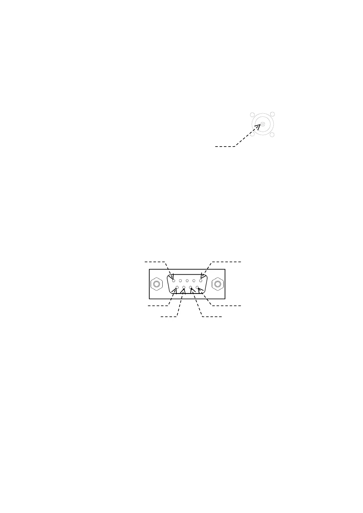
⑦ RS–422 Connector
Connections from an IBS/INS device are to be plugged into this receptacle. A
D–Sub 9 female type plug mates with this connector. The pin assignments are
illustrated below.
Figure 7-12 RS–422 Connector Pin Assignments (Front View)
NOTES:
(1) This interface consists of a MAX3490 RS–422 transceiver. Brief specs. are given
below. For details, see the parts manufacturer’s (MAXIM ) data sheets.
Input High Voltage : 2V (min.), Input Low Voltage : 0.8V (max.)
Input Current ( signal lines A & B ) : 1.0 mA @12V, –0.8 mA @ –7V
Receiver Input Impedance: 12 kΩ
(2) Pins #1, #2, #3 and #4 : No internal connections
(NC)
(3) Input lines (pins #6 and #7) are insulated from ship’s ground by opto–isolators.
・ Mating Plug: HDEB–9S (supplied) or equivalent
After making connections, check to be sure that the RS–422 port is enabled (as per
paragraph 4.11.2) and that a correct set of parameters is selected (as per
paragraphs 4.11.3 and 4.11.4) for your applications.
The command formats used to control communications with an INS/IBS device are
given in paragraph 7.4.
(
continued on next page
)
490/4209.5 kHz
+12
V at center conductor
Pin #1 (NC) Pin# 5 (GND)
6 ( RX+), Sig. Line A
9 (TX–), Sig. Line B
7 ( RX–), Sig. Line B
8 ( TX+), Sig. Line A