4
P5415479
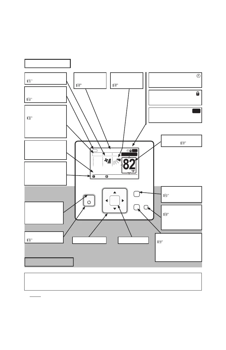
2. Switch Names and Functions
The fi gure below shows all the functions for reference. The actual display during operation is different.
NOTE:
Make sure to press the buttons lightly with your fi ngertips. Do NOT press the buttons or anything with
sharp points, such as a ball point pen. The operational functionality of the controller may become
damaged.
Display Part
OK
Menu
Back/Help
ECO
On/Off
A/C
MODE SPEED
TEMP
COOL
LOUV. Adj.
Meeting Room
LOUV.
FLTR
Service Filter Indicator
FLTR
It is displayed at the set period for
fi lter cleaning.
Operation Lock Indicator
It is displayed when the operation
lock function is set.
Schedule Timer Indicator
It is displayed when the schedule
timer function is set.
Louver Swing
Indicator
( Page 8)
Directional Key Enter Key
On/Off Button
( Page 8)
Run Indicator
Lights while the unit
is operational, and it
fl ashes in abnormal
conditions.
Room Name
Indicator
( Page 35)
Operation Component
Temperature Setting
Indicator
( Page 7)
ECO Button
( Page 9)
Power saving can be
started or stopped by
pressing this switch.
Back/Help Button
( Page 37)
Used to return to the previous
screen or to display the Help
Menu when pressed from the
Normal Mode.
Menu Button
( Page 10)
To display the Menu.
Backlight
Backlight is turned ON by pressing any button. In an instance of using two controllers, only the fi rst
operated controller turns ON a backlight; the other does not turn ON backlight.
Fan Speed Indicator
( Page 7)
Operation Mode
Indicator
( Page 5)
The indications of “HEAT”
and “AUTO” are displayed
only for the heat pump
type models.
Operation Guide
Indicator
“Central Control” is displayed
while the remote control
operation is prohibited.
Ventilation Mode
Indicator
( Page 29)
Power Saving
Indicator
It is displayed when the
power saving function is set.