Hardware Installation—Installing the IFC-1010/2020
105
The XP Series Transponder provides the IFC-1010/2020 system with an
efficient multiplex subsystem capability and standalone operation in case
of failure. The XP Transponder communicates directly with the control
panel’s CPU along the SLC communications loop.
The XP Transponders are extremely effective in both high-rise and
low-rise buildings where power losses over long wiring distances dictate
the use of remote control equipment, amplifiers, or audio/visual power
supplies. Each XP Transponder may contain up to three expansion
modules, each with up to eight IDCs, NACs, or Form-C relays. To the
IFC-1010/2020, XP Transponder circuits appear as individual monitor or
control modules.
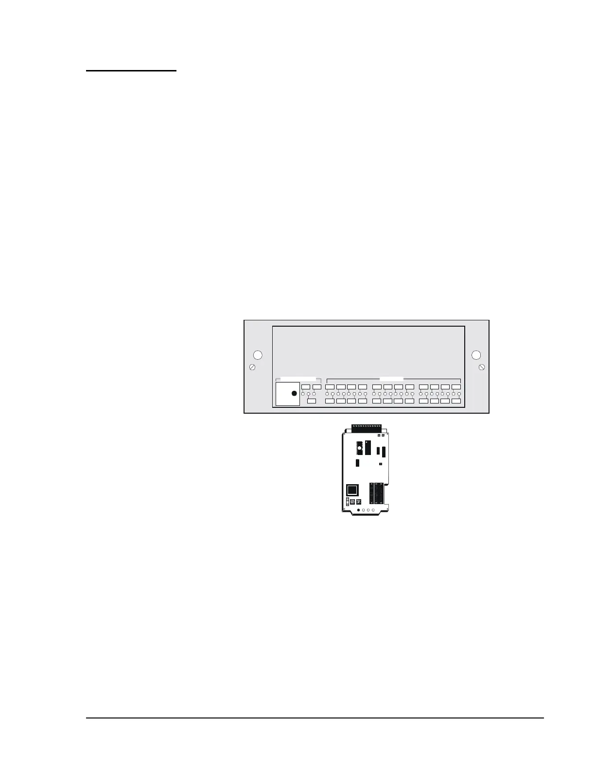
The BE-XP includes the XPP-1 Transponder Processor Module, an XPDP
dress panel (refer to Figure 76), a CHS-4 chassis, all required cables, and
instructions. The XPP-1 module provides two field-programmable
addressable dual Form-C relays.
N3
Press To:
Silence
Reset
Display
Troubles
Lamp Test
Transponder Status
1 3
2 4 6 8
75
12 14 16
15139 11
10 20 22 24
232117 19
18
Circuit Status
XP
TRANSPONDER
SERIES
xpdpxpp1
P3P2P1
JP2 JP3
JP4
12 11 10 9 8 7 6 5 4 3 2 1
XP Dress Panel (XPDP)
XPP-1 Module
Figure 76: XP Dress Panel and XPP-1 Module
Provides eight Class B or four Class A Notification Appliance Circuits.
For audio evacuation applications, the XPC-8 can drive eight speaker
circuits Style Y (Class B) or four Style Z (Class A), or can be alternately
configured to control and annunciate fireman’s telephone circuits.
XP Series
Transponder
BE-XP
Transponder
Starter
Complement
(Power-limited)
XPC-8 Control
Module
(Power-limited)