Hardware Installation—Installing the IFC-1010/2020
59
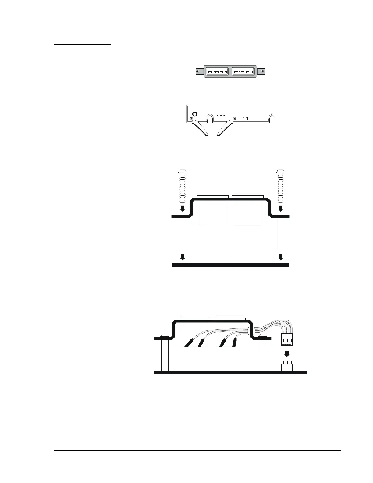
The optional Main Power Meter (MPM-2) may only be installed on the
main power supply, MPS-24A or MPS-24AE (refer to Figure 37).
DC A MPS
0 1 2 3
DC V OLTS
0 15 20 25 30 35
P7
Step 1
Remove the two screws in the bottom left-hand
corner of the MPS-24A or MPS-24AE.
Step 2
Thread the two replacement screws through the MPM-2
bracket and through the two standoffs provided. Place the
MPM-2 assembly over the MPS-24A and secure with the
two screws.
Step 3
Complete the installation of the MPM-2 by plugging the
female connector on the meter into Plug P7 on the
MPS-24A or MPS-24AE.
P7
mpminst
Figure 37: Installation of the Main Power Meter
Optional Main
Power Meter