Hardware Installation—Installing the IFC-1010/2020
27
Each component in the system has a specific mounting position in the
cabinet. Mount any optional AVPS supplies and amplifiers in
CHS-4/4L chassis Positions A through D as required. It is recommended
that the CHS-4/4L chassis always be installed in the lowest cabinet row
available (refer to Table 2).
Table 2: Cabinet Size Information
Cabinet Models Cabinet Rows
CAB-A3
1
CAB-B3
2
CAB-C3
3
CAB-D3
4
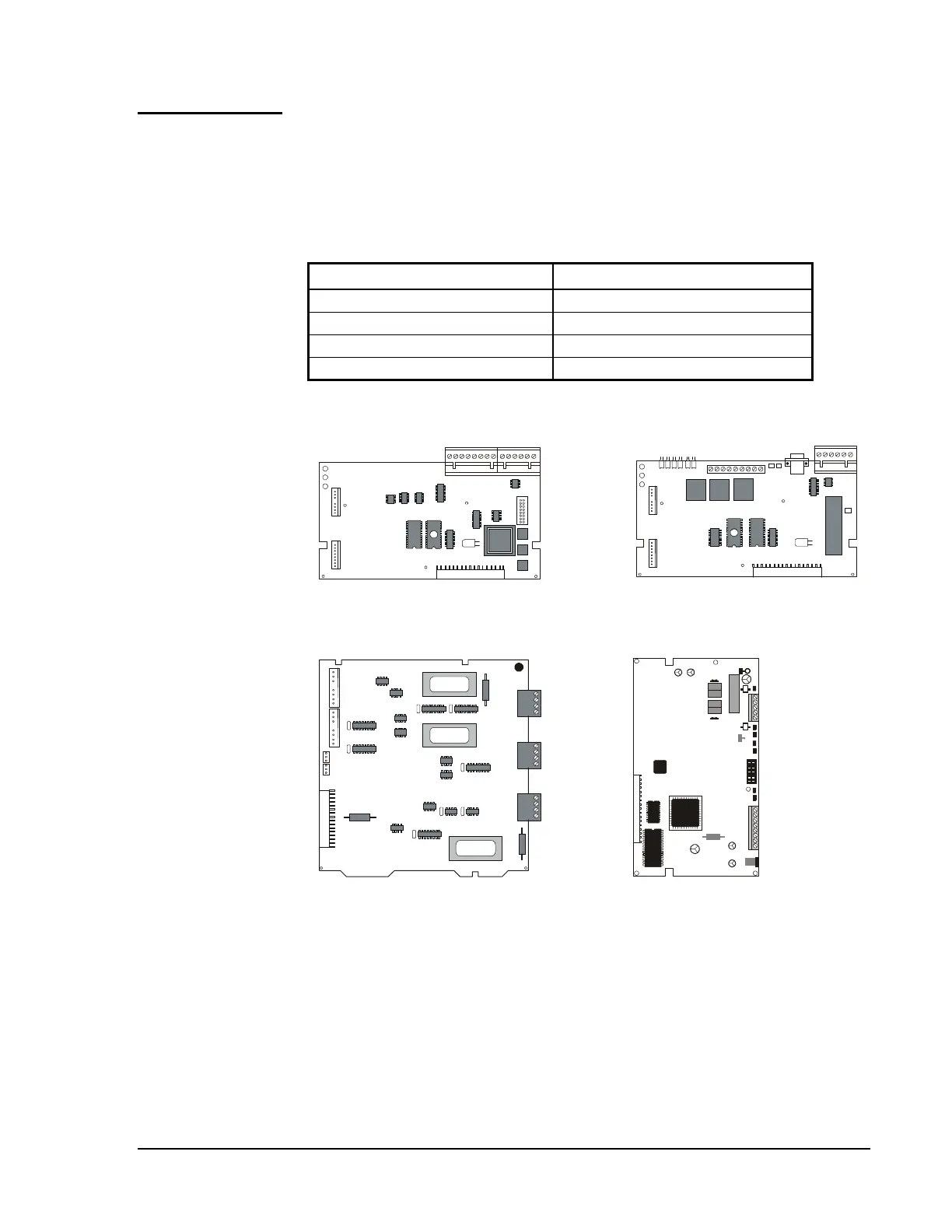
Optional component placement guidelines are provided
in Figure 19.
compplac
NIB-96
(Power-Limited)
Mounts in any one LIB position or any
two CHS-4/4L positions.
UZC-256
(Power-Limited)
Mounts in any one LIB position or any
two CHS-4/4L positions.
CCM-1
(Power-Limited)
Mounts in any one LIB position or any
two CHS-4/4L positions.
NAM-232
(Power-Limited)
Mounts in either the left or right position
of a CHS-4 by using four PEM studs on
the CHS-4 chassis.
Figure 19: Component Placement Guidelines
N33
Component
Placement