34
Hardware Installation—Installing the
IFC-1010/2020
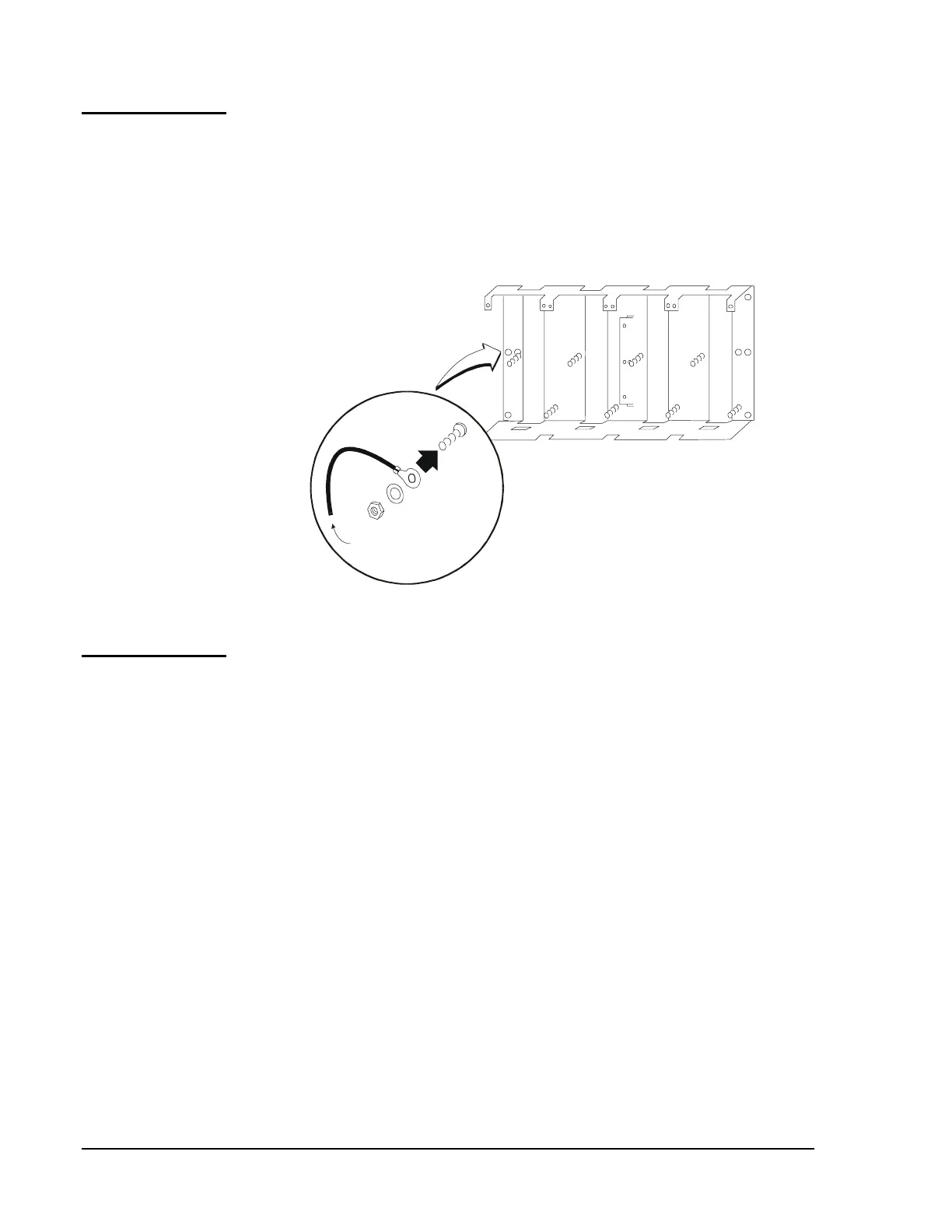
If employing an optional CHS-4/4L chassis (Figure 26), mount the chassis
in the lowest available row in the cabinet, below previously mounted
interconnect chassis assemblies (ICA-4L). The CHS-4/4L is marked to
identify the top of the chassis. Connect grounding wires of equipment to
be placed in the CHS-4/4L to the PEM stud indicated. Secure the unit to
the cabinet with the nuts and lock washers provided.
Note: The CAB-A3 cabinet will not accept an additional chassis.
CHS-4 Chassis
chsinst
Use Cable 71073
To Equpment Mounted
in CHS-4/4L
Figure 26: Optional Chassis Mount
The Display Interface Assembly (DIA) includes a backlit Liquid Crystal
Display (LCD), operator keypad, the Display Interface Board (DIB),
hinged dress panel, and the CPU to DIB cable. Only one DIA is required
per system. The DIA-2020 is included with the BE-2020 Basic Equipment
Package for the IFC-2020. The DIA-1010 is included with the BE-2020
Basic Equipment Package for the IFC-1010. Figure 27 depicts the
basic system.
N11
Optional
Chassis
Mounting
Other
Components
Display Interface
Assemblies