68
Hardware Installation—Installing the
IFC-1010/2020
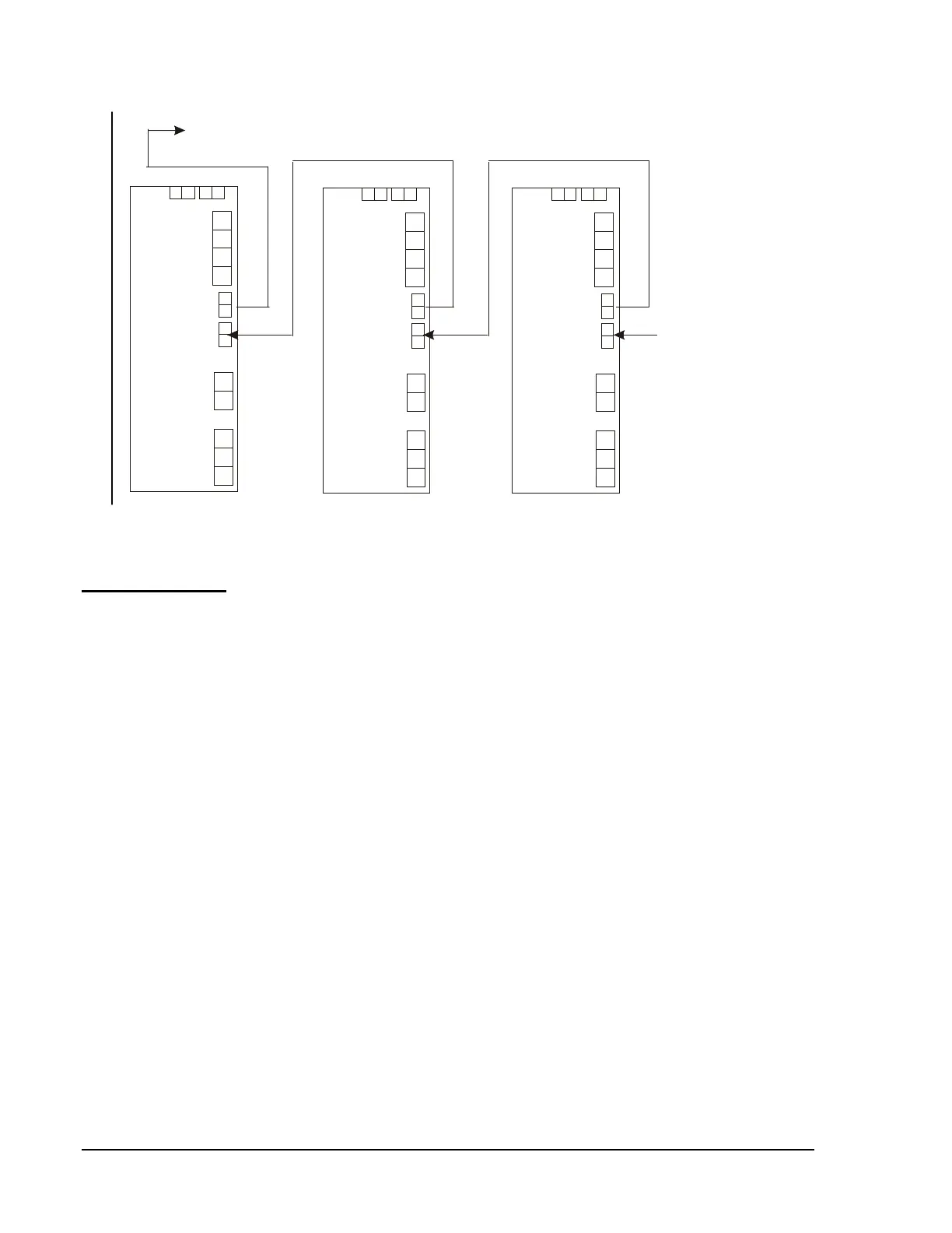
J3
J4
J3
J4
J3
J4
To trouble input on control panel:
IFC-2020 CPU-2020 P5, IFC-1010 CPU-2 P5, XPP-1 P6.
Cable 71033/75098
Cable 71033/75098
Cable 71033/75098
To AVPS-24 or AVPS-24E,
CCM-1, AMG-1, or
another APS-6R if these
devices are employed.
Aps6rbus
Figure 45: Trouble Bus Connections for Multiple APS-6R
Power Supply Configuration
N23
The Central Processing Unit is the heart of the system (refer to
Figure 46). This unit directs all communications between modules and
monitors all modules in the system for removal or failure. The CPU
maintains all programmable system parameters (except alphanumeric
information) in nonvolatile memory to protect the data if primary and
secondary power is removed (provided the board and all associated cabling
is handled with proper precaution). The CPU executes all control-by-event
programs for specific programs for specific action in response to an alarm
condition. A realtime clock provides time annotation on the displays and
printer. The CPU provides one set of Form-C general alarm contacts and
one set of Form-C system trouble contacts. The Form-C general alarm
contacts will transfer during the presence of one or more fire alarm signals.
The Form-C system trouble contacts will transfer during any security
alarm, supervisory signal, or trouble condition. Only one CPU is required
per IFC-1010/2020 system.
Central
Processing
Unit
(CPU-2020,
CPU-2)