36
Hardware Installation—Installing the
IFC-1010/2020
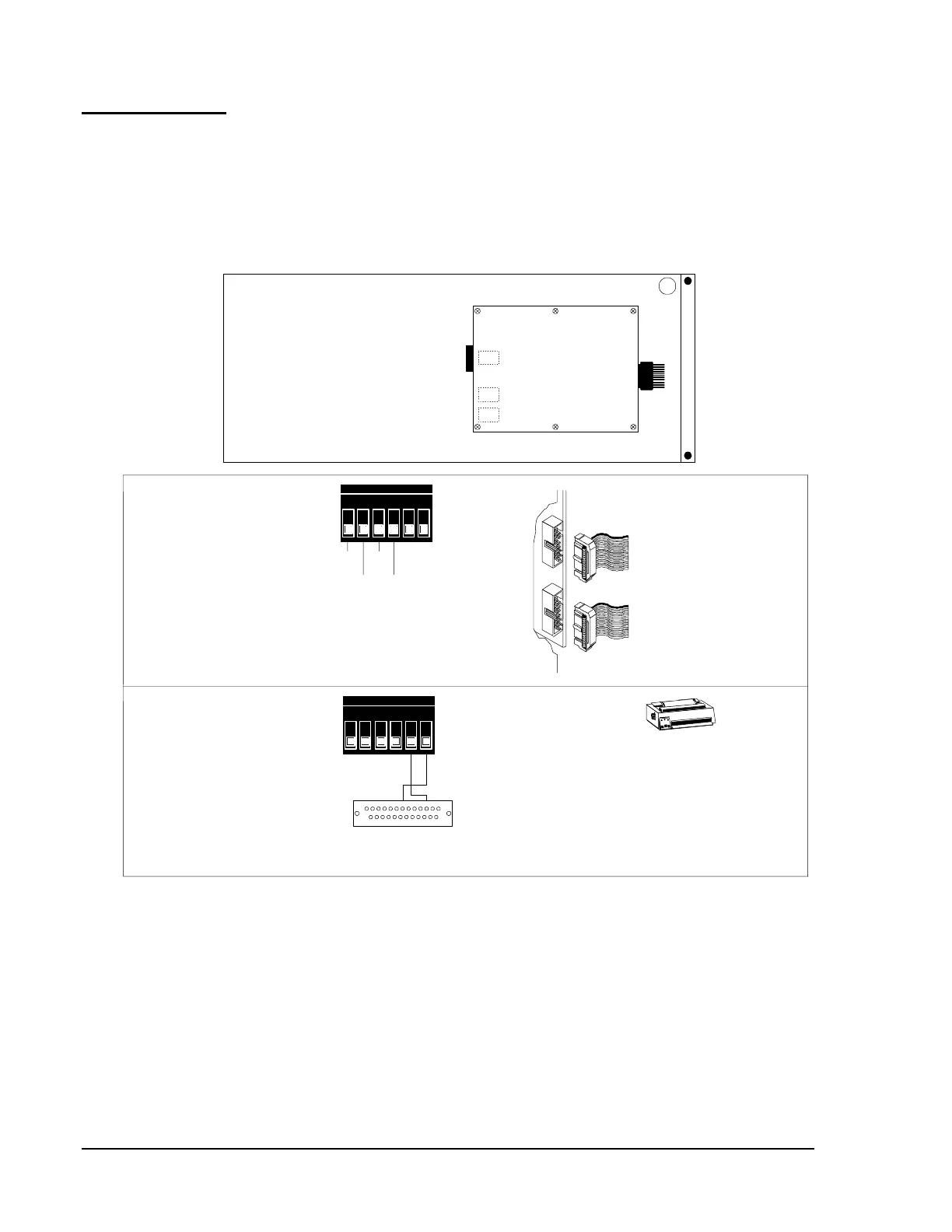
DIA-1010 and/or DIA-2020 provide access to the system CPU and the
optional SIB, and an EIA-232 unsupervised printer interface (Figure 28).
When terminal supervision is not required and the terminal
N13
(if present)
has no keyboard, the DIA-1010 and/or DIA-2020 provide an EIA-485
interface, which may be used to connect an LCD-80 (in Terminal mode).
3217
Display Interface Assembly (DIA-1010/DIA-2020)
The plug-in terminal block TB1 may
be removed to facilitate field printer
connections (see below).
TB1
J3
J4
Display Interface Board
(DIB)
TB1
(+)
Return
(+)
Out
(-)
Return
(-)
Out
EIA-485 to LCD-80
If a supervised CRT-1 or CRT-1 with keyboard has been
installed, this interface cannot be used. TheCCM-1
Communications Converter Module must be employed to
connect the LCD-80 in terminal mode. Refer to the
for details.
LCD-80 Liquid Crystal DisplayTechnical Bulletin, (LIT-445151)
DIB J3
DIB J4
Connect ribbon cable
75226 from DIB J3
to CPU P3.
Connect ribbon cable
71046 from DIB J4
to SIB P4.
diaconn
EIA-232 to PRN-3, or
Keltron Printer No. VS4095/5
Outputs are power-limited, but not supervised or
opto-isolated. Connections must be made with overall
foil/braided-shield twisted paired cable suitable for EIA-232
and EIA-485 applications. The printer must be installed in
the same room as the control panel. Terminate the shield
at the cabinet entrance only.
Plug this DB-25 connector into the RS-232 port of
the PRN-3 printer, or Keltron Printer No. VS4095/5.
TB1
All terminals are
power-limited.
Transmit
to Printer
EIA-232
Reference
N17 N16
N13
N14 N15
Figure 28: Display Interface Assembly
N13, N14, N15, N16, N17
Display
Interface
Connection