Hardware Installation—Installing the IFC-1010/2020
61
The remote battery charger, CHG-120, is capable of charging
25-120 ampere hour batteries. This unit is required if the MPS-24A must
deliver more than 3 amperes of current when no fire signal is present.
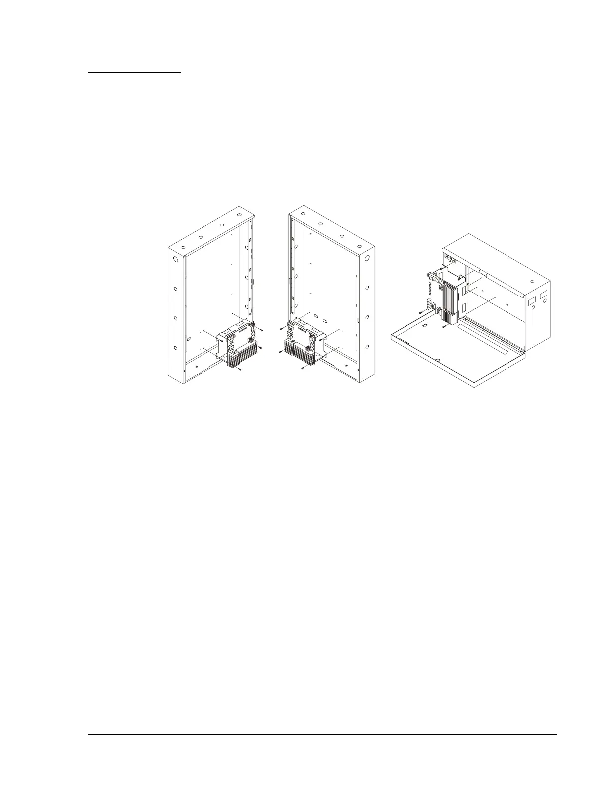
Batteries up to 120 AH can be housed with the charger in the
BB-55 cabinet: Batteries up to 25 AH can be housed with the charger in
cabinets CAB-A3, -B3, -C3, or –D3. Refer to Figure 39 for installation
positions. The charger can be mounted up to 20 feet (6.096 meters) away
from the control panel. To determine the battery size needed in a particular
system, refer to Table 5.
Chg120 Install
Figure 39: CHG-120 Installation into CAB-3 Series and
BB-55 Cabinets
With the breaker at the main power distribution panel turned off, connect
the primary power source to the corresponding terminal on TB1 of the
CHG-120. All connections between IFC-1010/2020 and the CHG-120
must be made in conduit, using 12 AWG (3.25 mm
2
) wire. Do not route
AC wiring in the same conduit as other control panel circuits. Leave the
main power breaker off until installation of the entire system is complete.
Do not apply AC power or batteries until the system is completely wired
and ready for testing.
CHG-120
Remote Battery
Charger
Connecting the
Primary Power
Source
Connecting the
Secondary
Power Source